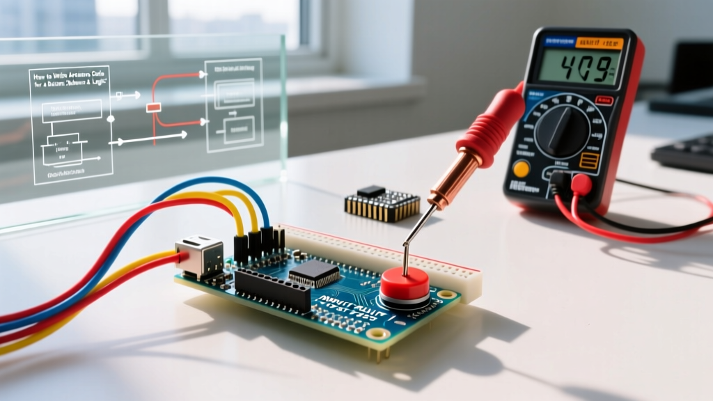

The Deceptive Simplicity of Push Buttons
Writing Arduino code for a button is often the second thing a beginner learns, right after blinking an LED. The logic seems trivial: if the pin reads HIGH, the button is pressed; if LOW, it is released. However, treating a mechanical switch as a perfect, instantaneous digital signal is one of the most common traps in embedded programming. In reality, physical contacts bounce, wires act as antennas, and naive polling loops freeze your entire microcontroller.
In this guide, we will move past the basic digitalRead() tutorial and explore how to write robust, non-blocking button logic. We will cover hardware wiring strategies, the physics of switch bounce, non-blocking millis() debouncing, and state-change detection for edge triggering. Whether you are using a classic ATmega328P-based Uno R3 or a modern RP2040-based board, these principles remain the bedrock of reliable human-machine interface (HMI) design in 2026.
Hardware Wiring: Pull-Up vs. Pull-Down
Before writing a single line of code, the physical circuit must be electrically stable. A microcontroller pin configured as an input has a very high impedance (often >100MΩ). If left disconnected ("floating"), it will pick up ambient electromagnetic noise, causing random phantom triggers.
To prevent this, we use a resistor to "pull" the pin to a known voltage state when the button is open.
- External Pull-Down Resistor: A 10kΩ resistor connects the input pin to GND. The button connects the pin to 5V (or 3.3V). When unpressed, the pin reads LOW. When pressed, it reads HIGH. This requires extra breadboard wiring and an additional component.
- Internal Pull-Up Resistor: Modern microcontrollers, including the ATmega328P, feature internal pull-up resistors (typically ranging from 20kΩ to 50kΩ). By wiring the button between the input pin and GND, and enabling the internal resistor in software, the pin reads HIGH when unpressed and LOW when pressed. This is the industry-standard approach for simple tactile switches as it reduces BOM cost and wiring complexity.
According to SparkFun's pull-up resistor tutorial, floating pins can cause erratic behavior and increased power consumption due to internal CMOS transistors rapidly switching states. Always use a pull-up or pull-down resistor.
The Physics of Switch Bounce
When you press a standard 6x6mm Omron B3F tactile switch or a Cherry MX mechanical keyboard switch, the metal contacts do not close cleanly. The physical impact causes the contacts to bounce against each other like a tuning fork before settling. This mechanical bouncing typically lasts between 1 millisecond and 20 milliseconds.
While 20ms is imperceptible to a human, a 16MHz Arduino executes roughly 16,000 instructions per millisecond. During that 20ms bounce window, the microcontroller will read dozens of rapid HIGH-LOW-HIGH transitions. If your code increments a counter on every button press, a single physical tap might register as 15 separate presses.
As detailed in Jack Ganssle's definitive guide to debouncing, switch bounce is an unavoidable mechanical reality that must be handled either via hardware filtering (RC circuits) or software state machines.
Method 1: The Blocking Delay (The Beginner Trap)
Most beginner tutorials solve bounce using the delay() function. While it works for simple tests, it is considered bad practice in production firmware.
const int btnPin = 2;

void setup() {
  pinMode(btnPin, INPUT_PULLUP);
  Serial.begin(115200);
}

void loop() {
  bool buttonState = digitalRead(btnPin);
  if (buttonState == LOW) {
    Serial.println("Button Pressed!");
    delay(50); // Blocks the CPU for 50ms to wait out the bounce
  }
}
The Problem: The delay(50) function halts the microcontroller. During those 50 milliseconds, your Arduino cannot read sensors, update displays, or manage motor control. In a complex 2026 IoT project, blocking the main loop leads to missed data packets and unresponsive UIs.
Method 2: Non-Blocking Millis() Debounce
The professional approach uses the millis() timer to track time without stopping the CPU. We record the exact time the pin state changes and ignore any subsequent changes until the debounce window (e.g., 50ms) has passed.
const int btnPin = 2;
bool lastStableState = HIGH;
bool currentReading = HIGH;
unsigned long lastDebounceTime = 0;
unsigned long debounceDelay = 50; // 50ms window

void setup() {
  pinMode(btnPin, INPUT_PULLUP);
  Serial.begin(115200);
}

void loop() {
  currentReading = digitalRead(btnPin);

  // If the switch changed, reset the debouncing timer
  if (currentReading != lastStableState) {
    lastDebounceTime = millis();
  }

  // Check if the debounce delay has passed
  if ((millis() - lastDebounceTime) > debounceDelay) {
    // If the state actually changed after the delay
    if (currentReading != lastStableState) {
      lastStableState = currentReading;

      // Trigger action only on a stable LOW (pressed)
      if (lastStableState == LOW) {
        Serial.println("Stable Press Registered!");
      }
    }
  }
}
This non-blocking architecture allows your loop() to run thousands of times per second, keeping the rest of your application responsive while silently filtering out mechanical noise in the background.
State Change Detection: Edge vs. Level Triggering
Another critical concept when writing Arduino code for a button is understanding the difference between level triggering and edge triggering.
- Level Triggering: The code reacts as long as the button is held down. If you hold the button for 2 seconds, and your loop runs every 10ms, your action will trigger 200 times.
- Edge Triggering (State Change): The code reacts only to the transition (the exact millisecond the button goes from unpressed to pressed). Holding the button does nothing after the initial trigger.
For toggling an LED or incrementing a menu setting, edge triggering is mandatory. The Arduino StateChangeDetection documentation outlines how to store the previous loop's state to detect this transition.
bool previousState = HIGH;

void loop() {
  bool currentState = digitalRead(btnPin);

  // Detect the exact moment of transition (Falling Edge)
  if (previousState == HIGH && currentState == LOW) {
    Serial.println("Edge Detected: Button just pressed!");
  }

  previousState = currentState; // Update for next loop
}
Note: For production environments, you must combine this edge-detection logic with the millis() debounce logic shown in Method 2 to prevent the edge from triggering multiple times during the mechanical bounce phase.
Comparison Matrix: Debouncing Strategies
Depending on your project constraints, you may choose different methods to handle button inputs. Below is a comparison of the most common strategies used in modern microcontroller design.
| Strategy | Implementation | CPU Overhead | Latency | Best Use Case |
|---|---|---|---|---|
| Blocking Delay | delay(50) |
High (Blocks CPU) | 50ms | Simple classroom demos, single-task scripts |
| Software Millis() | State machine with millis() |
Very Low | 20-50ms | Standard UI buttons, menu navigation, IoT devices |
| Hardware RC Filter | 10kΩ Resistor + 0.1µF Capacitor | Zero | ~10ms | High-vibration environments, interrupt-driven wakeups |
| Dedicated IC | MAX6816 or similar debounce IC | Zero | Configurable | Medical devices, automotive, mission-critical HMI |
| RTOS Task | FreeRTOS task with vTaskDelay |
Low (Yields core) | 20-50ms | ESP32/RP2040 multi-core applications |
Advanced Pro-Tips for 2026 Maker Workflows
- Use Established Libraries for Complex UIs: While writing your own debounce logic is an essential learning milestone, production projects with multiple buttons should leverage optimized libraries like
OneButtonorButton2. These libraries handle single clicks, double clicks, and long-press holds out of the box using non-blocking state machines. - Interrupts vs. Polling: Avoid using hardware interrupts (
attachInterrupt()) for standard push buttons unless the MCU is in deep sleep. Mechanical bounce can trigger the interrupt service routine (ISR) multiple times, and software debouncing inside an ISR is highly discouraged. Polling viamillis()in the main loop is safer and more predictable. - Capacitive Touch Alternatives: If your project is housed in a sealed, waterproof enclosure, consider replacing mechanical tactile switches with capacitive touch sensors (like the TTP223 module). These eliminate mechanical bounce entirely, though they require different threshold-tuning logic in software.
Summary
Mastering button inputs is about bridging the gap between the messy physical world and the precise digital realm. By utilizing internal pull-up resistors, abandoning blocking delays in favor of millis() state machines, and implementing proper edge-triggering logic, your Arduino projects will transition from fragile prototypes to robust, responsive devices.