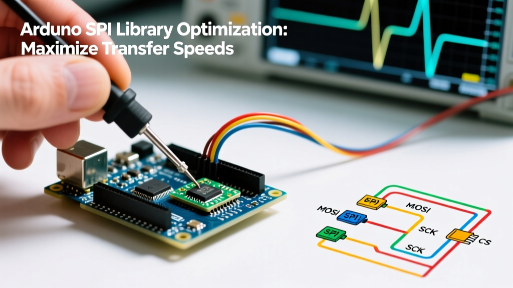

The Hidden Bottleneck in Default SPI Implementations
When prototyping with microcontrollers, the Arduino Official SPI Tutorial provides a straightforward way to communicate with sensors, displays, and memory chips. However, the default examples prioritize simplicity over performance. As of 2026, with the proliferation of high-resolution ADCs, fast FRAM modules, and TFT displays requiring massive data payloads, relying on naive SPI implementations will severely throttle your project's throughput.
The core issue lies in how the standard SPI.transfer() function is often misused. By treating the Arduino SPI library as a simple byte-pusher inside a standard for loop, developers inadvertently introduce massive CPU overhead, preventing the hardware from reaching its theoretical maximum clock speeds. True performance optimization requires a multi-tiered approach: leveraging buffer transfers, mastering clock boundaries, and utilizing Direct Memory Access (DMA).
Level 1: Buffer Transfers vs. Byte-by-Byte Iteration
The most common performance killer in embedded SPI code is the byte-by-byte transfer loop. Every time you call SPI.transfer(uint8_t), the microcontroller must execute a function call, push registers to the stack, interact with the SPI data register (SPDR), wait for the transfer complete flag (SPIF), and return. On an ATmega328P (Arduino Uno) running at 16 MHz, this software overhead takes longer than the actual hardware shifting of the bits.
The Naive Approach (Slow)
uint8_t payload[512];
// ... payload populated ...
digitalWrite(CS_PIN, LOW);
for (int i = 0; i < 512; i++) {
    SPI.transfer(payload[i]); // Massive function call overhead per byte
}
digitalWrite(CS_PIN, HIGH);
The Optimized Approach (Fast)
The Arduino SPI Reference documents a buffer transfer method that passes a pointer and a size. This allows the underlying C++ core library to use a tightly optimized while loop, and on advanced architectures, it automatically engages the hardware FIFO (First-In-First-Out) buffers or DMA triggers.
uint8_t payload[512];
// ... payload populated ...
digitalWrite(CS_PIN, LOW);
SPI.transfer(payload, 512); // Single function call, optimized core execution
digitalWrite(CS_PIN, HIGH);
On an Arduino Zero (SAMD21), switching from a byte-by-byte loop to the buffer method can increase effective throughput by over 300%, simply by eliminating the repeated function call and stack manipulation overhead.
Level 2: Mastering SPISettings and Clock Boundaries
Many legacy tutorials still reference SPI.setClockDivider(). This is deprecated and dangerous in multi-device environments. The modern standard is SPISettings, used in conjunction with SPI.beginTransaction(). This ensures that the SPI bus is configured atomically, preventing conflicts if an interrupt service routine (ISR) attempts to use a different SPI device simultaneously.
However, setting the clock speed requires understanding your specific microcontroller's hardware limits. The number you pass to SPISettings is a maximum request; the Arduino SPI library will silently round down to the nearest valid hardware prescaler.
| Microcontroller Board | Core Architecture | Max Theoretical SPI | Practical Reliable Limit | Optimal SPISettings (Hz) |
|---|---|---|---|---|
| Arduino Uno / Nano | AVR (ATmega328P) | 8 MHz (F_CPU/2) | 4 - 8 MHz | 8000000 |
| Arduino Zero / MKR | ARM Cortex-M0+ (SAMD21) | 24 MHz | 12 - 24 MHz | 12000000 |
| Nano 33 BLE Sense | ARM Cortex-M4 (nRF52840) | 32 MHz | 16 - 32 MHz | 16000000 |
| Teensy 4.1 | ARM Cortex-M7 (i.MX RT1062) | 120 MHz | 30 - 60 MHz | 30000000 |
Pro Tip: Always verify the actual clock output with an oscilloscope or logic analyzer. If you request 20 MHz on an AVR, the library divides the 16 MHz system clock by 2, yielding 8 MHz. If you request 10 MHz on a SAMD21, the SERCOM peripheral calculates the baud rate based on the generic clock (GCLK), which might result in 12 MHz or 8 MHz depending on the exact GCLK divisor configured in the board's variant files.
Level 3: Direct Memory Access (DMA) for Zero-CPU Transfers
For applications requiring continuous, high-speed data streaming—such as reading from an external 16-bit ADC at 1 MSPS or pushing pixel data to an ILI9341 display—polling the SPI status register is inefficient. DMA allows the SPI peripheral to pull data directly from SRAM and push it to the MOSI pin without any CPU intervention.
The standard Arduino SPI library abstracts DMA differently depending on the board support package (BSP):
- AVR (Uno/Mega): True DMA is not available on the ATmega328P. You must rely on SPI Interrupts (
SPI.attachInterrupt()), though the 1-byte hardware buffer limits the effectiveness of this approach. - SAMD21/SAMD51 (Zero/Feather M4): The SERCOM peripheral has dedicated DMA triggers. While the default
SPI.transfer(buf, len)uses a tight polling loop, advanced libraries likeAdafruit_ZeroDMAor direct register manipulation can offload this to the DMAC controller. - Teensy 4.x: As detailed in the PJRC Teensy SPI Documentation, the underlying hardware utilizes an enhanced DMA (eDMA) system. By using the
SPI.transfer()buffer method alongsideEventResponderor theAsyncSPIlibraries, the Cortex-M7 core can execute complex DSP algorithms while the SPI bus transfers megabytes of data in the background.
Hardware Reality: When Software Optimization Hits Physics
You can write the most perfectly optimized DMA-driven SPI code in the world, but if your hardware layout is flawed, your data will be corrupted. High-speed SPI is highly susceptible to signal integrity issues.
The 10 MHz Breadboard Wall: Never attempt to run SPI above 4 MHz on a standard solderless breadboard. The parasitic capacitance between the breadboard's internal metal clips (often 2-5 pF per node) combined with the inductance of long jumper wires creates severe RC delay and ringing on the SCK and MOSI lines, leading to bit-shift errors.
When pushing the Arduino SPI library beyond 12 MHz on custom PCBs or perfboards, you must implement the following hardware mitigations:
- Series Termination Resistors: Place 33Ω to 47Ω resistors in series with the SCK and MOSI lines, as close to the master MCU as possible. This dampens high-frequency ringing caused by impedance mismatches.
- Ground Return Paths: For every SPI signal wire in a ribbon cable or harness, there must be an adjacent ground wire. This minimizes the loop area, reducing both electromagnetic interference (EMI) and ground bounce.
- MISO Capacitance: If you have multiple slaves on the same MISO line, the input capacitance of each unselected slave's MISO pin adds up. At 20 MHz+, this can slow the rise time of the MISO signal. Use a bus switch IC (like the SN74LVC1G3157) or tri-state buffers to isolate unselected devices.
Final Optimization Checklist
Before finalizing your firmware for production, run through this SPI optimization checklist:
- Replace all
forloop byte transfers withSPI.transfer(buffer, size). - Wrap all SPI transactions in
SPI.beginTransaction()andSPI.endTransaction()using explicitSPISettings. - Verify the SPI Mode (CPOL/CPHA) matches the target peripheral's datasheet exactly; Mode 0 and Mode 3 are most common, but a mismatch will silently corrupt data.
- Measure the actual SCK frequency with a logic analyzer to ensure the hardware prescaler is matching your expectations.
- Inspect your physical wiring for parasitic capacitance and add series termination resistors if operating above 8 MHz.
By respecting both the software architecture of the Arduino SPI library and the physical realities of high-speed digital signaling, you can reliably push microcontroller peripherals to their absolute limits, ensuring your 2026 embedded projects perform flawlessly under heavy data loads.