
Understanding the 13.56 MHz RFID Ecosystem
Building an access control system, an automated attendance logger, or a smart inventory tracker starts with a fundamental component: the arduino rfid reader. For beginners, the MFRC522 module is the undisputed gateway into Radio Frequency Identification (RFID). Operating at 13.56 MHz, this module complies with the ISO/IEC 14443 Type A standard, allowing it to communicate seamlessly with MIFARE Classic 1K, MIFARE Ultralight, and NTAG21x transponders.
Unlike optical barcode scanners that require line-of-sight, RFID utilizes electromagnetic fields to power passive tags and extract their Unique Identifier (UID). In 2026, the RC522 remains a staple in DIY electronics due to its low cost (typically $2.50 to $4.00 per unit) and robust support within the Arduino IDE ecosystem via the Serial Peripheral Interface (SPI) protocol.
Hardware Selection: RC522 vs. PN532
Before writing a single line of C++, it is critical to verify you have the correct hardware for your target tags. A common beginner mistake is attempting to read a 125 kHz EM4100 key fob with a 13.56 MHz RC522 module. Physics dictates this will fail silently.
| Feature | MFRC522 (RC522 Module) | PN532 (NFC Module) |
|---|---|---|
| Operating Frequency | 13.56 MHz | 13.56 MHz |
| Primary Protocol | ISO 14443A (MIFARE) | ISO 14443A/B, FeliCa, NFC |
| Smartphone Interaction | No (Cannot read/write NFC phones) | Yes (Supports NFC P2P & Tag emulation) |
| Average Price (2026) | $2.50 - $4.00 | $7.00 - $12.00 |
| Best Use Case | Basic UID scanning, MIFARE sector read/write | NFC payment emulation, smartphone pairing |
Exact SPI Wiring for 5V Microcontrollers
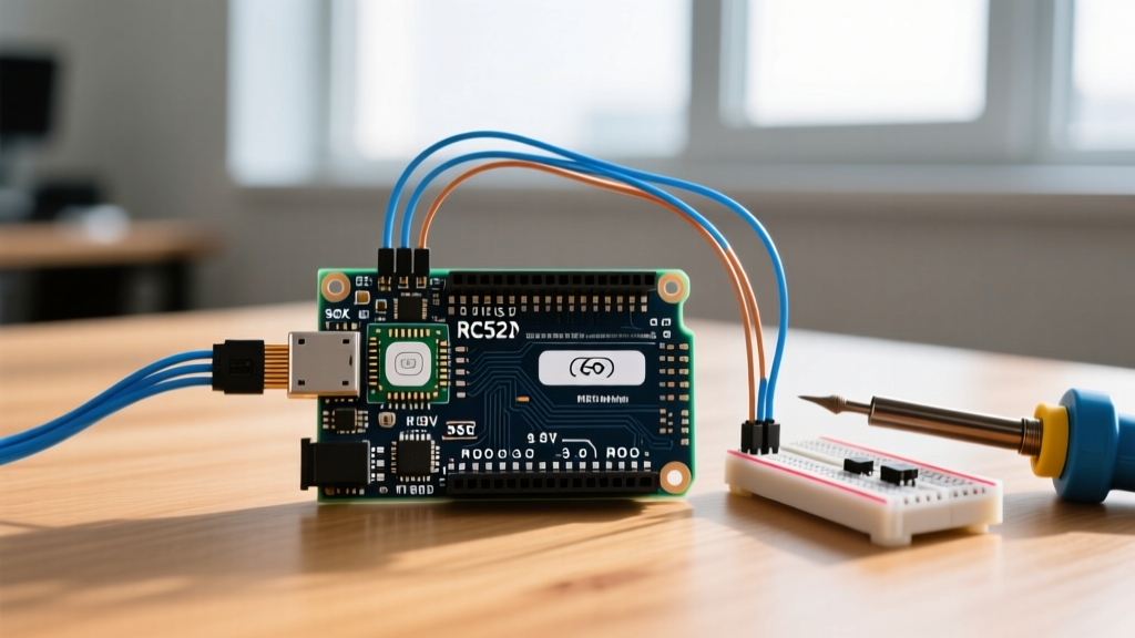
The MFRC522 IC communicates via SPI. While the Arduino Uno and Nano operate at 5V logic, the RC522 module is strictly a 3.3V device. Supplying 5V to the VCC pin will permanently destroy the silicon. Furthermore, while the module's MISO pin is generally 5V tolerant, sending 5V logic from the Arduino's MOSI and SCK pins into the 3.3V RC522 inputs can degrade the chip over time. For permanent installations, use a bidirectional logic level shifter (like the BSS138). For breadboard prototyping, direct connection often works, but proceed with an understanding of the electrical stress.
⚠️ Critical Warning: Never connect the RC522 VCC pin to the Arduino 5V pin. Always use the 3.3V output. If your Arduino's 3.3V regulator cannot supply the required 130mA peak current during RF transmission, the module will brownout and fail to initialize.
SPI Pin Mapping Table
| RC522 Pin | Arduino Uno / Nano Pin | Function / Notes |
|---|---|---|
| SDA (SS) | 10 | Slave Select (Configurable in code) |
| SCK | 13 | SPI Clock |
| MOSI | 11 | Master Out Slave In |
| MISO | 12 | Master In Slave Out |
| IRQ | Not Connected | Interrupt pin (Unused in basic polling) |
| GND | GND | Common Ground |
| RST | 9 | Reset (Configurable in code) |
| 3.3V | 3.3V | Power Supply (Max 130mA) |
Arduino IDE Setup and Library Installation
To abstract the complex ISO14443A handshake and CRC (Cyclic Redundancy Check) calculations, we utilize the MFRC522 library. In Arduino IDE 2.3.x (the standard for 2026), navigate to Sketch > Include Library > Manage Libraries. Search for "MFRC522" by GithubCommunity (originally by Miguel Balboa) and install version 1.4.11 or newer. This library handles the SPI clock division automatically, keeping the SPI bus speed under the 10 MHz maximum supported by the RC522 silicon.
Core C++ Firmware: Extracting the UID
The following code initializes the SPI bus, wakes the MFRC522 frontend, and continuously polls for new 13.56 MHz tags. When a MIFARE or NTAG card enters the RF field, the module powers the tag's micro-coil, executes an anti-collision loop, and retrieves the UID.
#include
#include

#define SS_PIN 10
#define RST_PIN 9

MFRC522 rfid(SS_PIN, RST_PIN);

void setup() {
  Serial.begin(9600);
  while (!Serial); // Wait for serial port on Leonardo/Micro

  SPI.begin();
  rfid.PCD_Init(); // Initialize the MFRC522 chip

  // Verify firmware version to ensure SPI wiring is correct
  byte version = rfid.PCD_ReadRegister(rfid.VersionReg);
  Serial.print("RC522 Firmware Version: 0x");
  Serial.println(version, HEX);

  if (version == 0x00 || version == 0xFF) {
    Serial.println("ERROR: Communication failure. Check SPI wiring and 3.3V power.");
  } else {
    Serial.println("RC522 Ready. Scan a 13.56 MHz tag.");
  }
}

void loop() {
  // Look for new cards
  if (!rfid.PICC_IsNewCardPresent()) return;

  // Select one of the cards
  if (!rfid.PICC_ReadCardSerial()) return;

  Serial.print("UID Found (Size ");
  Serial.print(rfid.uid.size);
  Serial.print(" bytes): ");

  // Print UID in Hexadecimal format
  for (byte i = 0; i < rfid.uid.size; i++) {
    if (rfid.uid.uidByte[i] < 0x10) Serial.print("0");
    Serial.print(rfid.uid.uidByte[i], HEX);
    Serial.print(" ");
  }
  Serial.println();

  // Halt the PICC and stop crypto operations
  rfid.PICC_HaltA();
  rfid.PCD_StopCrypto1();
}
Decoding the Serial Output and BCC
When you open the Serial Monitor at 9600 baud and tap a MIFARE Classic 1K tag, you will see an output similar to: UID Found (Size 4 bytes): A3 4F 1C 8E.
As a programmer, you must understand that a 4-byte UID actually consists of 3 bytes of data and 1 byte of BCC (Block Check Character). The BCC is a simple XOR checksum of the first three bytes, designed to prevent transmission errors during the anti-collision phase. If you are storing UIDs in a database for access control, it is best practice to store the entire 4-byte array (or 7-byte array for NTAGs) to ensure absolute uniqueness across different manufacturing batches.
Advanced Troubleshooting and Edge Cases
Beginners frequently encounter silent failures when deploying an arduino rfid reader. Use this diagnostic matrix to resolve hardware and environmental edge cases:
- Firmware Returns 0x00 or 0xFF: This indicates the Arduino is reading a floating SPI line. The MISO pin is not connected, or the RC522 is unpowered. Check your 3.3V rail and jumper wire integrity.
- Firmware Returns 0x91 or 0x92: This is the correct factory firmware version for the MFRC522 IC. Your SPI communication is healthy.
- Tag Fails to Read on Metal Surfaces: Placing the RC522 coil directly against a metal chassis causes eddy currents that detune the 13.56 MHz LC oscillator. You must use a ferrite shielding sheet or elevate the module at least 10mm away from conductive surfaces.
- Intermittent Reads / Dropouts: The standard jumper wires provided in beginner kits often have high contact resistance. If the 3.3V line drops below 3.0V during the RF transmission burst (which draws ~130mA), the RC522 will reset mid-scan. Soldering the header pins or using thicker gauge wires resolves this voltage sag.