
Beyond the Basics: Why the Default SPI Library Falls Short
When most makers first encounter the SPI library for Arduino, they learn a simplified workflow: call SPI.begin(), set the chip select pin LOW, and push bytes using SPI.transfer(). While this approach works for basic sensors at low clock speeds, it completely falls apart in complex, multi-device environments or when pushing high-speed peripherals like ILI9341 TFT displays and W5500 Ethernet modules. In 2026, modern embedded design demands a rigorous understanding of bus arbitration, signal integrity, and hardware-specific routing.
This deep dive moves past the beginner tutorials. We will dissect the SPISettings class, analyze the architectural differences between the ATmega328P and ESP32 SPI buses, and solve the high-frequency signal integrity issues that plague advanced DIY projects.
The Anatomy of SPISettings and Transactions
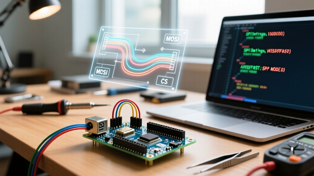
The most critical mistake in legacy Arduino code is the use of global configuration functions like SPI.setClockDivider() or SPI.setDataMode(). These functions alter the global state of the SPI bus. If you have an SD card module that requires SPI Mode 0 at 4MHz, and a MAX31856 thermocouple amplifier that requires SPI Mode 1 at 8MHz on the same bus, global configurations will cause intermittent data corruption.
The modern SPI standard implementation in Arduino relies on the SPISettings object and transaction blocks. This ensures thread-safe, conflict-free communication.
Expert Insight: Always wrap your SPI transfers inSPI.beginTransaction()andSPI.endTransaction(). This locks the bus, preventing interrupts or RTOS tasks on advanced MCUs from hijacking the SPI peripheral mid-transfer.
Decoding SPI Modes: CPOL and CPHA
The SPISettings constructor takes three arguments: clockSpeed, bitOrder, and dataMode. The data mode is dictated by Clock Polarity (CPOL) and Clock Phase (CPHA). Selecting the wrong mode is the number one cause of 'garbage data' on the MISO line.
| SPI Mode | CPOL (Idle Clock State) | CPHA (Sampling Edge) | Common IC Examples |
|---|---|---|---|
| SPI_MODE0 | LOW (0) | Leading (Rising) | W5500 Ethernet, ILI9341 TFT, ADXL345 |
| SPI_MODE1 | LOW (0) | Trailing (Falling) | MAX31856 Thermocouple, MAX6675 |
| SPI_MODE2 | HIGH (1) | Leading (Falling) | LSM6DS3 (Some configurations) |
| SPI_MODE3 | HIGH (1) | Trailing (Rising) | MAX31855, MAX7219 LED Driver |
When configuring your transaction, your code should look like this:
SPISettings mySettings(8000000, MSBFIRST, SPI_MODE1);SPI.beginTransaction(mySettings);// Perform transfersSPI.endTransaction();
Hardware Realities: ATmega328P vs. ESP32 Architectures
The SPI.h library abstracts the hardware, but the underlying silicon dictates your physical wiring and maximum throughput. Treating an ESP32 like an Arduino Uno is a fast track to hardware failure.
The ATmega328P (Arduino Uno/Nano)
The ATmega328P features a single hardware SPI peripheral tied to strict physical pins: MOSI (11), MISO (12), SCK (13), and SS (10). The maximum theoretical clock speed is half the system clock, meaning an 8MHz maximum on a standard 16MHz Uno. Attempting to use bit-banged software SPI on other pins for high-speed displays will result in severe CPU bottlenecking and screen tearing.
The ESP32 (SPI2 and SPI3 Buses)
The ESP32 completely changes the paradigm. It features three SPI buses. SPI1 is reserved for the onboard flash memory. SPI2 (often mapped to HSPI) and SPI3 (mapped to VSPI) are available for user peripherals. According to the ESP-IDF SPI Master API documentation, the ESP32 can push clock speeds up to 80MHz and supports advanced DMA (Direct Memory Access) double-buffering.
While the ESP32 allows you to map SPI to almost any GPIO via the GPIO matrix, doing so at speeds above 26MHz introduces routing delays. For 40MHz+ TFT displays, you must use the default VSPI pins: GPIO 18 (SCK), GPIO 19 (MISO), GPIO 23 (MOSI), and GPIO 5 (CS) to ensure signal integrity.
Signal Integrity and Edge Cases at High Clock Speeds
When you push the SPI library for Arduino beyond 10MHz, you stop dealing with purely digital logic and start dealing with RF transmission line physics. A common failure mode is 'ringing' on the SCK line, which causes the peripheral to register multiple false clock edges, shifting the entire data register by a bit.
The 5V to 3.3V Logic Level Trap
Connecting a 5V Arduino directly to the MISO/MOSI pins of a 3.3V module (like an ESP8266 or a modern SD card breakout) will slowly degrade the peripheral's silicon. Conversely, feeding 3.3V logic into a 5V ATmega328P MISO pin often fails because 3.3V is below the 5V logic HIGH threshold (typically 0.6 * VCC, or 3.0V minimum, leaving zero noise margin).
- Bad Solution: Using a simple resistor voltage divider. The parasitic capacitance of the resistor network will round off the square wave edges, destroying signals above 2MHz.
- Good Solution: Use a dedicated BSS138 MOSFET-based bidirectional logic level shifter module (costing roughly $1.20 per unit). It handles up to 10MHz reliably.
- Best Solution: For 20MHz+ SPI, use a Texas Instruments SN74LVC1T45 or CD4050 non-inverting buffer IC. These provide the sharp edge transitions required for high-speed clocking.
Series Termination Resistors
If you are wiring an SPI bus over a ribbon cable longer than 10cm, or running at 40MHz+ on an ESP32, you must add series termination resistors. Soldering a 33Ω to 47Ω resistor directly inline with the MOSI, MISO, and SCK lines (close to the Master's output pins) absorbs high-frequency reflections and eliminates clock ringing.
Advanced Troubleshooting Matrix
When the SPI library for Arduino returns 0xFF or 0x00 continuously, use this diagnostic matrix to isolate the failure mode.
| Symptom | Root Cause | Hardware/Software Fix |
|---|---|---|
Constant 0xFF reads | MISO line is floating; peripheral is not driving the bus. | Check Chip Select (CS) wiring. Ensure CS is pulled LOW before transfer. Verify peripheral has power. |
Constant 0x00 reads | MISO is shorted to ground, or Master is reading its own MOSI. | Check for solder bridges on MISO. Ensure MISO and MOSI are not swapped (a common breakout board silkscreen error). |
| Data is shifted by 1 bit | Wrong SPI Mode (CPOL/CPHA) or SCK ringing. | Verify IC datasheet for SPI Mode. Add 33Ω series resistor to SCK line to dampen reflections. |
| Intermittent corruption | Interrupts firing during SPI transfer, altering global registers. | Wrap transfers in SPI.beginTransaction(). Use SPI.usingInterrupt() if hardware interrupts interact with SPI pins. |
| Works on Uno, fails on ESP32 | ESP32 default SPI speed is too high for the peripheral. | Explicitly define SPISettings with a lower clock speed (e.g., 4000000) instead of relying on library defaults. |
Optimizing for the Future: DMA and RTOS
If you are writing code for the ESP32 using the Arduino core, you are running on top of FreeRTOS. The standard SPI.transfer() function is blocking; it halts the CPU until the byte is shifted out. When driving a 320x240 TFT display, pushing 153,600 pixels sequentially will starve your WiFi stack and cause network disconnects.
For advanced users, bypassing the Arduino SPI.h wrapper in favor of the native ESP-IDF spi_device_queue_trans() allows you to leverage DMA. By configuring a DMA buffer in RAM, the hardware handles the SPI shifting in the background, freeing the CPU to handle network packets or sensor polling. While this steps outside the standard Arduino library, understanding the limitations of SPI.h is the first step toward professional-grade firmware architecture.
Conclusion
Mastering the SPI library for Arduino requires moving beyond copy-pasted setup code. By strictly utilizing SPISettings for bus arbitration, respecting the physical limitations of your microcontroller's silicon, and applying proper RF signal integrity practices to your wiring, you can eliminate the ghost-in-the-machine bugs that plague complex DIY electronics. Whether you are routing high-speed data on an ESP32 or managing multiple sensors on an ATmega328P, disciplined SPI management is the hallmark of expert embedded design.