
The First Line of Defense: Why Every I2C Project Needs a Scanner
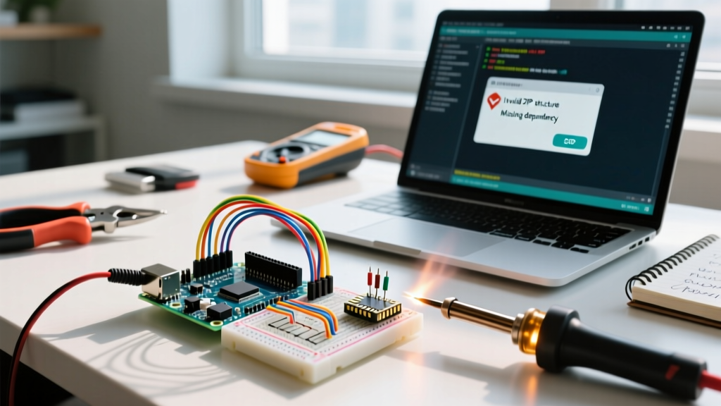
When integrating new sensors, displays, or actuators into a microcontroller ecosystem, the Inter-Integrated Circuit (I2C) bus is often the default choice. However, the moment a new module fails to respond, developers are left guessing: Is it a wiring fault? A missing pull-up resistor? Or simply an undocumented hexadecimal address? This is where the classic i2c scanner arduino sketch becomes an indispensable diagnostic tool.
In 2026, with the proliferation of high-density sensor hubs and advanced MCUs like the ESP32-S3 and Raspberry Pi Pico 2, I2C bus topologies have grown increasingly complex. Relying solely on a basic serial printout is no longer sufficient for robust hardware debugging. This deep dive explores the mechanics of I2C scanning, advanced library alternatives, and the hardware edge cases that cause scanners to fail or hang.
Anatomy of the Standard I2C Scanner Arduino Sketch
The foundational I2C scanner relies on the native Arduino Wire library. It iterates through all 127 possible 7-bit I2C addresses (0x01 to 0x7F), initiates a transmission, and listens for an acknowledgment (ACK) or a negative acknowledgment (NACK).
While the standard sketch provided in the Arduino IDE examples is a great starting point, understanding the return codes of the Wire.endTransmission() function is where true debugging begins.
Decoding Wire.endTransmission() Return Codes
Most basic tutorials only check if the return value is 0. However, the Wire library returns specific error codes that pinpoint exactly where the bus is failing:
- 0: Success. The device acknowledged its address.
- 1: Data too long to fit in the transmit buffer (rare in scanning, common in data payloads).
- 2: Received NACK on transmit of address. (The device is not present at this address).
- 3: Received NACK on transmit of data. (The device is present, but rejected the data byte).
- 4: Other error (e.g., bus collision, arbitration lost, or hardware timeout).
Beyond the Basics: Advanced I2C Diagnostic Libraries
The standard sketch has a fatal flaw: if the SDA line is pulled low by a locked-up slave device, the Wire.begin() function can hang indefinitely, freezing your microcontroller. To bypass this, expert developers turn to advanced diagnostic libraries.
Rob Tillaart’s I2CScanner Library
The I2CScanner library by Rob Tillaart is a massive upgrade over the default sketch. It introduces non-blocking scans, bus recovery routines, and detailed device mapping. Key features include:
- Bus Recovery: Automatically toggles the SCL line to release a stuck SDA line caused by a slave device mid-transmission.
- Ping vs. Check: Differentiates between a simple address ping and a full register-read check to verify device health, not just presence.
- Speed Testing: Iterates through Standard (100kHz), Fast (400kHz), and Fast-Plus (1MHz) modes to find the maximum stable bus speed for your specific wiring capacitance.
Hardware Edge Cases: Why the Scanner Finds Nothing
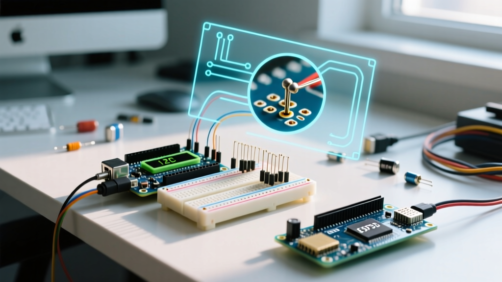
Software can only do so much. If your i2c scanner arduino sketch returns zero devices, the issue is almost certainly physical. According to the official NXP I2C Bus Specification (UM10204), I2C is an open-drain architecture. This means devices can only pull the line LOW; they rely on external pull-up resistors to bring the line HIGH.
The Pull-Up Resistor & Capacitance Matrix
Selecting the wrong pull-up resistor is the most common cause of I2C failure. The resistor value must be calculated based on the bus capacitance and the desired clock speed.
| I2C Speed Mode | Max Bus Capacitance | Recommended Pull-Up (3.3V) | Recommended Pull-Up (5V) | Common Failure Symptom |
|---|---|---|---|---|
| Standard (100 kHz) | 400 pF | 4.7 kΩ | 4.7 kΩ | Scanner finds devices, but data reads are corrupted. |
| Fast (400 kHz) | 400 pF | 2.2 kΩ | 3.3 kΩ | Scanner hangs or returns Error 4 (Timeout/Collision). |
| Fast-Plus (1 MHz) | 550 pF | 1.0 kΩ | 1.5 kΩ | Rise times are too slow; NACK on address. |
Pro-Tip for 2026 Prototyping: Many modern breakout boards (like Adafruit's Stemma QT or SparkFun's Qwiic ecosystem) include onboard 4.7kΩ pull-up resistors. If you daisy-chain more than three of these modules, the parallel resistance drops below 1.5kΩ, which can exceed the maximum sink current (typically 3mA to 20mA) of your microcontroller's GPIO pins, leading to logic level degradation and phantom addresses on the scanner.
Resolving Address Conflicts and Multiplexing
What happens when your project requires two identical sensors, like dual BME688 environmental monitors, but both are hardcoded to address 0x76 or 0x77? An I2C scanner will only show one address, and data collisions will corrupt your readings.
The TCA9548A I2C Multiplexer Solution
The Texas Instruments TCA9548A is an 8-channel I2C multiplexer that sits on the main bus (default address 0x70). It allows you to create up to 8 isolated sub-buses. To scan devices behind a multiplexer, your Arduino code must first send a command to the TCA9548A to open a specific channel, run the I2C scanner loop, close the channel, and move to the next.
This technique is mandatory for complex robotics or multi-zone environmental monitoring where identical sensor arrays are required.
Step-by-Step Troubleshooting Flowchart
When your i2c scanner arduino output is blank or erratic, follow this strict diagnostic sequence:
- Verify Power: Use a multimeter to confirm 3.3V or 5V at the sensor's VCC pin. A floating ground is a frequent culprit.
- Check Pull-Ups: Measure resistance between SDA/SCL and VCC. If it reads >10kΩ or OL (Open Loop), you are missing pull-ups. Add 4.7kΩ resistors.
- Logic Level Mismatch: If connecting a 5V Arduino Mega to a 3.3V ESP32 or sensor, use a bidirectional logic level shifter (like the BSS138 MOSFET circuit). Direct connections can fry the slave device's SDA pin, causing it to permanently pull the bus low.
- Reduce Clock Speed: Force the bus to 10kHz using
Wire.setClock(10000);. If the scanner suddenly finds the device, your bus capacitance is too high for 400kHz. Use thicker wires or an I2C bus extender IC like the PCA9600. - Run Bus Recovery: If the scanner hangs on the first iteration, manually toggle the SCL pin as a standard GPIO output 9 times to clear any stuck slave states, then reinitialize
Wire.begin().
Frequently Asked Questions (FAQ)
Why does my I2C scanner show addresses that aren't connected?
Phantom addresses usually occur due to bus noise, missing pull-up resistors, or a floating SDA line. Without pull-ups, the SDA line can drift into an indeterminate state, causing the microcontroller to misinterpret noise as an ACK signal. Always ensure 4.7kΩ pull-ups are present.
Can I use the internal pull-ups of the ATmega328P or ESP32?
While microcontrollers have internal pull-ups (typically 20kΩ to 50kΩ), they are far too weak for reliable I2C communication. The weak pull-up results in extremely slow rise times, violating the I2C timing specifications at 400kHz. Always use external physical resistors for production or reliable prototyping.
My scanner finds the OLED display but not the MPU6050 IMU. Why?
The MPU6050 requires a specific initialization sequence and sometimes a stable 3.3V logic level to respond correctly to address pings. Furthermore, if the AD0 pin is floating, it may default to an unexpected state. Tie the AD0 pin explicitly to GND (for address 0x68) or VCC (for address 0x69) and ensure adequate decoupling capacitors (100nF) are placed near the IMU's power pins.
Conclusion
Mastering the i2c scanner arduino workflow is about looking past the simple serial output and understanding the electrical realities of the open-drain bus. By leveraging advanced diagnostic libraries, calculating proper pull-up resistances, and utilizing multiplexers for address conflicts, you can transform I2C from a source of endless frustration into a robust, high-speed communication backbone for your 2026 embedded projects.