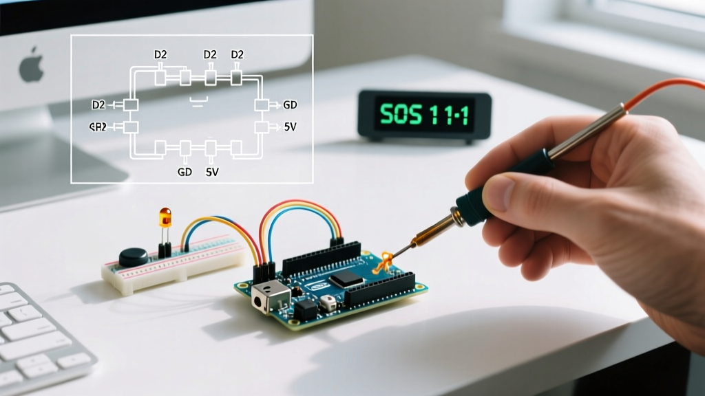

The Mathematics of CW: Why Timing is Everything
In the modern era of high-bandwidth IoT, Continuous Wave (CW) or Morse code might seem archaic. Yet, in 2026, ultra-low-power sub-GHz RF meshes and emergency LoRa beaconing still rely on CW for its unparalleled signal-to-noise ratio and minimal bandwidth footprint. When programming Arduino Morse code applications, the most critical failure point for beginners is timing drift caused by blocking functions.
According to the American Radio Relay League (ARRL), standard Morse timing is based on the 'PARIS' word model. The fundamental unit is the 'dot' (dit). A dash (dah) is three dot lengths. The space between elements of a single letter is one dot length, between letters is three, and between words is seven.
The 20 WPM Standard: At 20 Words Per Minute (WPM), a single dot lasts exactly 60 milliseconds. If your Arduino sketch uses
delay(60)to generate a dot, you are ignoring execution time, serial buffer processing, and RF module state changes, resulting in severe timing degradation and unreadable CW at the receiver.
Library Spotlight: MorseEnDecoder Architecture
While many developers attempt to write their own lookup tables, the MorseEnDecoder library, originally authored by Mark VandeWettering, remains the gold standard for non-blocking CW operations. As documented in the MorseEnDecoder GitHub repository, the library utilizes a finite state machine (FSM) that evaluates pin states on every iteration of the loop() function without halting the CPU.
Core Object Mechanics
The library instantiates objects that track internal state variables. For encoding, it parses a string into a bit-shifted integer array, pulling one bit at a time based on millis() deltas. For decoding, it measures the duration of logic HIGH and LOW states to classify them as dots, dashes, or spaces, ultimately mapping them back to ASCII characters.
- Memory Footprint: Approximately 1.8 KB of flash and 120 bytes of SRAM, making it viable for ATtiny85 and Arduino Nano constraints.
- Character Set: Full ITU-R M.1677-1 standard alphanumeric support, plus common prosigns (e.g.,
SK,AR). - Non-Blocking I/O: Fully compatible with concurrent sensor polling and WiFi stack maintenance.
Hardware Topologies for RF and Audio
Generating Morse code in software is only half the battle; physical layer modulation dictates your success. Below are the two most common hardware configurations for Arduino-based CW projects.
1. Sub-GHz RF Telemetry (433 MHz)
For long-range, low-power beaconing, the FS1000A transmitter and XY-MK-5V receiver pair is standard. Transmitter Wiring (Arduino Nano 33 IoT):
- VCC: 5V (Do not use 3.3V; RF output drops by 60%).
- GND: Common ground with the MCU.
- DATA (ATAD): Pin D4 (configured as OUTPUT in the library).
Pro-Tip: Solder a 17.3 cm (6.8 inch) 22 AWG copper wire to the ANT pad on the FS1000A. This acts as a quarter-wave monopole antenna, increasing effective radiated power (ERP) by up to 15 dBm compared to the bare spring antenna.
2. Audio Frequency Decoding (700 Hz - 1000 Hz)
When decoding Morse from a ham radio transceiver's headphone jack or a piezo sensor, you must condition the audio signal. The Arduino's ADC cannot read negative AC voltage swings.
- Op-Amp Biasing: Use an LM358 dual op-amp to shift the AC audio signal to a 1.65V DC offset.
- Envelope Detection: Pass the signal through a 1N4148 diode and a 100nF capacitor to extract the CW envelope.
- Schmitt Trigger: Feed the envelope into a 74HC14 to convert the analog ramp into a crisp digital square wave for the Arduino interrupt pin.
Interrupt-Driven Decoding: Why Polling Fails
If you attempt to decode Morse code using digitalRead() inside the main loop, you will miss state changes at speeds above 15 WPM, especially if your loop includes I2C sensor reads or OLED display updates. Following the Arduino BlinkWithoutDelay paradigm is mandatory for the transmitter, but the receiver must use hardware interrupts.
void setup() {
  // Pin 2 on Arduino Uno/Nano supports hardware interrupts (INT0)
  pinMode(2, INPUT_PULLUP);
  attachInterrupt(digitalPinToInterrupt(2), cw_isr, CHANGE);
}

volatile unsigned long last_change = 0;
volatile unsigned long pulse_duration = 0;

void cw_isr() {
  unsigned long current_time = micros();
  pulse_duration = current_time - last_change;
  last_change = current_time;
  // Pass pulse_duration to the MorseEnDecoder state machine
}
By using micros() inside the Interrupt Service Routine (ISR), you capture transitions with 4-microsecond precision, ensuring flawless decoding even at 35 WPM (where a dot is merely 34ms).
Blocking vs. Non-Blocking: A Performance Matrix
Choosing the wrong architectural approach will cripple your IoT node. Here is how the MorseEnDecoder library compares to naive blocking implementations.
| Metric | Naive Delay-Based (Blocking) | MorseEnDecoder (Non-Blocking FSM) |
|---|---|---|
| CPU Availability | 0% during transmission | 99% (only uses cycles on state change) |
| Max Concurrent Tasks | None (WiFi/Sensors stall) | Unlimited (I2C, SPI, UART safe) |
| Timing Accuracy (20 WPM) | ±15ms drift per character | ±1ms (bound by millis() resolution) |
| Watchdog Timer (WDT) Resets | Frequent (if message > 2 seconds) | None (loop continues to feed WDT) |
Advanced Edge Cases: Farnsworth Timing and RF Drift
When deploying Arduino Morse code for educational tools or automated repeater IDs, you may encounter two advanced edge cases:
1. Farnsworth Timing Implementation
Standard timing keeps the ratio of dots, dashes, and spaces fixed. However, learners often struggle to recognize characters at high speeds. Farnsworth timing sends the characters at a high speed (e.g., 25 WPM) but inserts extended inter-character and inter-word spaces to lower the overall effective WPM to 10. The base MorseEnDecoder library requires a minor fork to separate char_speed from effective_speed variables, allowing you to multiply the space durations by a Farnsworth scalar without altering the internal dot/dash ratios.
2. 433MHz OOK Drift and Preamble Starvation
When using cheap OOK (On-Off Keying) RF modules like the FS1000A, the receiver's Automatic Gain Control (AGC) requires a preamble to lock onto the noise floor. If your Arduino starts transmitting a CW string immediately, the first two or three characters (e.g., 'CQ') will be swallowed by the receiver's AGC settling time. Solution: Always prepend your Morse string with 16 to 32 alternating dots and dashes (e.g., ...---...---) to train the XY-MK-5V receiver's op-amp before sending the actual payload.
Real-World Troubleshooting Guide
Even with a robust library, physical layer anomalies will occur. Use this diagnostic checklist when your CW signal degrades:
- Symptom: Receiver decodes dots as dashes.
Fix: Your transmitter'smillis()timer is overflowing, or your RF module is overheating and delaying the transistor switching time. Add a 10k pull-down resistor on the RF DATA line to ensure hard LOW states. - Symptom: Decoded text has random duplicate characters.
Fix: Contact bounce on a manual straight key or mechanical relay. Implement a 5ms software debounce in your ISR before registering the state change. - Symptom: WiFi drops out during CW transmission on ESP8266/ESP32.
Fix: The RF harmonics from an unshielded 433MHz module are desensitizing the 2.4GHz WiFi antenna. Move the CW antenna at least 15 cm away from the ESP32 PCB, or wrap the RF module in copper tape grounded to the MCU GND.
By leveraging non-blocking state machines and respecting the physics of RF modulation, your Arduino Morse code projects can achieve military-grade reliability for emergency mesh networks and low-power telemetry.