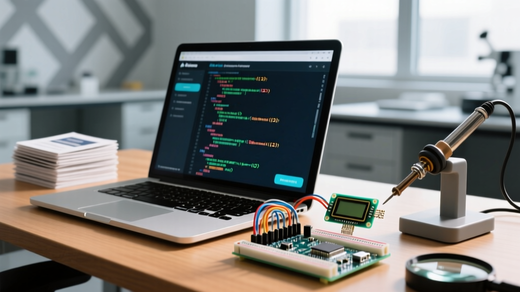

In 2026, AI-assisted programming has become a standard workflow for embedded systems engineers. However, when dealing with hardware communication protocols like I2C, SPI, and UART, software syntax is only half the battle. The physical layer—bus capacitance, pull-up resistor values, and clock stretching—dictates whether your code will actually work on the bench. This guide explores how to effectively use an AI Arduino code generator to build robust I2C communication setups, bridging the gap between AI-generated logic and real-world electrical constraints.
The Physical Layer Gap: Where AI Fails
Large Language Models (LLMs) are trained on millions of lines of open-source code. Unfortunately, much of that code is written for idealized conditions or legacy 5V AVR microcontrollers. When you ask a generic AI Arduino code generator to write an I2C script for a modern 3.3V ESP32-S3, it frequently hallucinates hardware configurations that will cause immediate bus lockups.
For example, the NXP I2C-bus specification and user manual (UM10204) strictly defines the 400pF bus capacitance limit and the necessity of external pull-up resistors for Fast Mode (400kHz). AI models often ignore these electrical realities, assuming internal microcontroller pull-ups are sufficient. When you rely on internal pull-ups (often 20kΩ to 50kΩ), the RC rise time of the SDA/SCL lines degrades, resulting in corrupted bytes and NACK (Negative Acknowledgment) errors.
Expert Insight: Never ask an AI to "write I2C code for Arduino." Ask it to "write a non-blocking I2C state machine for an ESP32-S3 reading a BME280 at 0x77, using 400kHz fast mode, with explicit Wire.endTransmission() error handling for NACKs and timeouts."
The Hardware Reality Check: What AI Hallucinates
To use an AI Arduino code generator effectively, you must anticipate its blind spots. Below is a matrix of common AI assumptions versus the hardware realities you must enforce in your prompts.
| Failure Mode | AI's Typical Assumption | Hardware Reality & Fix |
|---|---|---|
| Missing Pull-Ups | Assumes internal microcontroller pull-ups are sufficient. | Internal pull-ups are too weak for 400kHz. Use external 2.2kΩ resistors to 3.3V. |
| Default Pin Mapping | Hardcodes SDA to A4 and SCL to A5 (AVR legacy). | ESP32-S3 defaults vary by board. Always explicitly define pins in Wire.begin(SDA, SCL). |
| Blocking Delays | Uses delay() between sensor reads. |
Blocks the RTOS core on ESP32, causing WiFi stack crashes. Use millis() or FreeRTOS tasks. |
| Ignored Return Codes | Assumes Wire.requestFrom() always succeeds. |
Must check the byte count returned and handle bus lockups via I2C bus recovery routines. |
Step-by-Step: Prompting the AI for Robust I2C Code
To extract production-ready firmware from an AI, you must provide a structured prompt that includes the microcontroller, the peripheral, the electrical constraints, and the error-handling requirements.
Step 1: Define the Physical and Logical Parameters
Your prompt must specify the exact hardware. For this guide, we are using an ESP32-S3-WROOM-1 development board (typically $5.00 - $7.00 in 2026) communicating with a Bosch BME280 environmental sensor.
- Microcontroller: ESP32-S3 (Dual-core, 3.3V logic)
- Sensor: BME280 (I2C Address: 0x76 or 0x77 depending on SDO pin state)
- Clock Speed: 400 kHz (Fast Mode)
- Pull-ups: 2.2kΩ external to 3.3V
Step 2: Demand Explicit Error Handling
The most critical part of I2C communication is handling bus errors. According to the official Arduino Wire library documentation, Wire.endTransmission() returns specific integer codes that AI often forgets to implement:
- 0: Success
- 1: Data too long to fit in transmit buffer
- 2: Received NACK on transmit of address
- 3: Received NACK on transmit of data
- 4: Other error
- 5: Timeout
Step 3: The Master Prompt Template
Copy and paste this exact framework into your preferred AI tool:
Act as an expert embedded systems engineer. Write a C++ Arduino sketch for an ESP32-S3 reading a Bosch BME280 sensor via I2C.
Constraints:
1. Use the Adafruit_BME280 library but wrap the reading function in a custom non-blocking state machine using millis().
2. Explicitly define I2C pins (SDA=GPIO8, SCL=GPIO9) and set Wire clock to 400000.
3. Implement robust error handling for Wire.endTransmission() and Wire.requestFrom(), specifically catching NACKs (codes 2 and 3) and Timeouts (code 5).
4. If a timeout occurs, implement an I2C bus recovery sequence (toggling SCL 9 times) before re-initializing the Wire library.
5. Do not use delay(). Output clean, commented, production-ready code.
Analyzing the AI-Generated Output
When you feed the above prompt to a top-tier AI Arduino code generator, it will produce a state-machine-based sketch. Here is a breakdown of the critical I2C recovery logic the AI should generate, which separates amateur code from professional firmware:
void recoverI2CBus() {
  Serial.println("[I2C] Bus lockup detected. Attempting recovery...");
  Wire.end(); // Shut down I2C peripheral

  // Configure SCL as output and toggle 9 times to release stuck SDA line
  pinMode(SCL_PIN, OUTPUT);
  for (int i = 0; i < 9; i++) {
    digitalWrite(SCL_PIN, LOW);
    delayMicroseconds(5); // Half clock cycle at 100kHz
    digitalWrite(SCL_PIN, HIGH);
    delayMicroseconds(5);
  }

  pinMode(SDA_PIN, INPUT_PULLUP); // Release SDA
  pinMode(SCL_PIN, INPUT_PULLUP); // Release SCL

  Wire.begin(SDA_PIN, SCL_PIN);
  Wire.setClock(400000);
  Serial.println("[I2C] Bus recovery complete.");
}
Why this matters: If a sensor resets or loses power mid-transaction, it may hold the SDA line LOW, locking the entire I2C bus. The AI-generated recovery routine above manually clocks the SCL line to force the slave device to release SDA. This is a vital edge-case fix that generic prompts will completely miss. For deeper insights into sensor initialization, always cross-reference the Bosch BME280 Datasheet to verify register addresses and timing delays.
Validating the Code with Hardware Tools
Never trust an AI Arduino code generator blindly. You must validate the physical layer. In 2026, you have two primary options for I2C debugging:
- Professional Logic Analyzer: The Saleae Logic Pro 8 (approx. $1,199) offers pristine I2C decoding, analog voltage overlays, and hardware triggering on NACKs.
- Budget Clone Analyzers: A generic 24MHz 8-channel logic analyzer (approx. $12 - $18 on Amazon/AliExpress) running PulseView/Sigrok. While the sample rate is lower, it is perfectly adequate for decoding 100kHz and 400kHz I2C traffic.
Validation Checklist
Connect your logic analyzer to SDA and SCL. Trigger on the falling edge of SCL. Verify the following:
- Rise Times: Ensure the SDA/SCL rise times are under 300ns for 400kHz Fast Mode. If they are slower, your pull-up resistors are too weak or bus capacitance is too high.
- Address Acknowledgment: Look for the 9th clock cycle. The SDA line must be pulled LOW by the slave (the BME280) to indicate an ACK. If it stays HIGH, you have an addressing or wiring error.
- Clock Stretching: Some sensors hold SCL LOW while processing. Ensure your AI-generated code doesn't prematurely timeout during these legitimate hardware delays.
Conclusion
In embedded systems, the physical layer is just as important as the software. An AI Arduino code generator can save you hours of boilerplate coding, but it is your responsibility to enforce the electrical realities of the I2C bus. By using precise, constraint-driven prompts and validating the output with a logic analyzer, you can rapidly deploy robust communication setups for any IoT or robotics project.


