
The Hidden Trap of Mechanical Switches
When transitioning from blinking LEDs to reading physical inputs, writing reliable Arduino code for button interactions is a fundamental rite of passage. To a human, pressing a tactile switch feels like a single, instantaneous event. To a microcontroller running at 16 MHz, however, that same press looks like a chaotic flurry of dozens of rapid on-and-off transitions. This phenomenon, known as switch bounce, is the number one reason beginners struggle with erratic button behavior, such as a single press triggering a menu to skip forward five times.
In this comprehensive guide, we will dissect the hardware realities of tactile switches, compare wiring topologies, and write robust, non-blocking Arduino code to filter out the noise. As of 2026, while capacitive touch and solid-state buttons are gaining traction in consumer electronics, the mechanical tactile switch remains the undisputed king of DIY prototyping due to its tactile feedback and low cost—a 100-pack of generic 6x6x5mm tactile switches still costs roughly $4.50 online.
Hardware Wiring: Pull-Up vs. Pull-Down Resistors
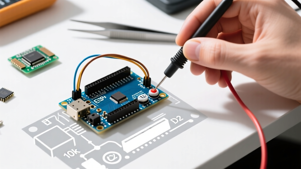
Before writing a single line of code, you must ensure your hardware is wired correctly. A microcontroller pin configured as an input has a very high impedance (essentially infinite resistance). If left unconnected to a defined voltage, it becomes a "floating pin," acting as an antenna that picks up ambient electromagnetic interference (EMI). To prevent this, we use resistors to "pull" the pin to a known state.
| Wiring Method | Circuit Topology | Logic State (Unpressed) | Logic State (Pressed) | Best Use Case |
|---|---|---|---|---|
| External Pull-Down | 10kΩ resistor to GND; Switch to 5V | LOW (0V) | HIGH (5V) | When active-HIGH logic is strictly required by external ICs. |
| External Pull-Up | 10kΩ resistor to 5V; Switch to GND | HIGH (5V) | LOW (0V) | Legacy circuits or when sharing a bus with specific logic gates. |
| Internal Pull-Up | Switch directly to GND; MCU enables internal resistor | HIGH (5V) | LOW (0V) | 95% of beginner and intermediate projects. Saves board space and components. |
For standard projects using the ATmega328P (the chip on the Arduino Uno R3 and Nano), we highly recommend using the Internal Pull-Up method. The ATmega328P features built-in pull-up resistors typically valued between 20kΩ and 50kΩ (nominally 30kΩ). By utilizing the INPUT_PULLUP mode in your setup function, you eliminate the need for external breadboard resistors, reducing points of failure. For a deeper dive into the physics of this topology, refer to SparkFun's comprehensive guide on pull-up resistors.
Understanding Switch Bounce (The 5ms Problem)
When the metal contacts inside a tactile switch (such as the popular Omron B3F series) collide, they do not settle instantly. The physical impact causes the contacts to microscopically bounce off one another before finally resting in the closed position. This mechanical vibration translates into electrical noise.
Expert Insight: According to industry testing, mechanical switch bounce typically lasts between 1ms and 5ms, though cheap or worn-out switches can bounce for up to 20ms. If your Arduino loop runs in 0.1ms, a single 5ms bounce event will be read as 50 separate button presses.
The most common beginner mistake is using the delay() function to wait out the bounce. While delay(50) will successfully ignore the bounce, it halts the entire microcontroller. During that 50 milliseconds, your Arduino cannot read sensors, update displays, or control motors. In professional embedded systems, blocking code is unacceptable. Instead, we use a non-blocking timing approach leveraging the millis() function, as outlined in Arduino's official debounce documentation.
Writing Non-Blocking Arduino Code for Button Debouncing
Below is the production-ready, non-blocking code for reading a button using the internal pull-up resistor. This script tracks the exact millisecond a state change occurs and ignores any subsequent changes until the debounce window has passed.
const int buttonPin = 2;          // Pin connected to the tactile switch
const int ledPin = 13;            // Onboard LED pin

int ledState = HIGH;              // Current state of the output LED
int buttonState;                  // Current reading from the input pin
int lastButtonState = HIGH;       // Previous reading from the input pin

unsigned long lastDebounceTime = 0;  // Last time the output pin was toggled
unsigned long debounceDelay = 50;    // Debounce time in milliseconds

void setup() {
  pinMode(buttonPin, INPUT_PULLUP); // Enable internal 30k pull-up resistor
  pinMode(ledPin, OUTPUT);
  digitalWrite(ledPin, ledState);
}

void loop() {
  int reading = digitalRead(buttonPin);

  // Check if the button state changed (due to noise or actual pressing)
  if (reading != lastButtonState) {
    // Reset the debouncing timer
    lastDebounceTime = millis();
  }

  // If the state has remained stable longer than the debounce delay
  if ((millis() - lastDebounceTime) > debounceDelay) {
    // If the button state has actually changed
    if (reading != buttonState) {
      buttonState = reading;

      // Toggle the LED only when the button transitions from HIGH to LOW (pressed)
      if (buttonState == LOW) {
        ledState = !ledState;
      }
    }
  }

  digitalWrite(ledPin, ledState);
  lastButtonState = reading; // Save the current reading for the next loop
}
Code Architecture Breakdown
- State-Change Detection: The code first checks if the current
readingdiffers from thelastButtonState. If it does, a potential press (or bounce) has occurred, and thelastDebounceTimetimer is reset to the currentmillis(). - The Rollover-Safe Math: Notice the conditional
(millis() - lastDebounceTime) > debounceDelay. This specific subtraction method is mathematically immune to the 32-bitmillis()rollover that occurs every 49.7 days. Never usemillis() > lastDebounceTime + debounceDelay, as it will fail catastrophically during a rollover event. - Edge Triggering: The LED toggles only when
buttonState == LOW. Because we are usingINPUT_PULLUP, a pressed button connects the pin to GND, pulling the logic level LOW. This ensures the LED toggles exactly once per physical press, rather than remaining on while the button is held down.
Production-Ready Alternative: The Bounce2 Library
While writing your own debounce logic is an excellent educational exercise, managing multiple buttons with custom millis() timers quickly bloats your sketch. For projects featuring keypads, rotary encoders, or multi-button interfaces, we strongly recommend the Bounce2 library. Available via the Arduino Library Manager, Bounce2 abstracts the timing math and provides clean methods like fell() (detects the exact moment a button is pressed) and rose() (detects release).
Using Bounce2 reduces the button-handling logic in your loop() to just three lines of code, freeing up cognitive load and memory for your core application logic. For a deeper technical analysis of switch noise and filtering algorithms, All About Circuits provides an excellent engineering breakdown of hardware vs. software solutions.
Troubleshooting Common Button Failures and Edge Cases
Even with perfect code, physical environments can introduce anomalies. If your Arduino code for button inputs is still behaving erratically, investigate the following edge cases:
- Long Wire Capacitance: If your button is connected via wires longer than 1 meter, the wire acts as a capacitor and an antenna. The internal 30kΩ pull-up resistor may be too weak to pull the line HIGH quickly enough, resulting in slow rise times that the MCU misinterprets. Fix: Add an external 4.7kΩ pull-up resistor at the MCU pin, or place a 100nF ceramic capacitor in parallel with the switch to absorb high-frequency EMI.
- Oxidized Contacts: Cheap tactile switches stored in humid environments develop oxidation on their metal contacts, leading to high contact resistance (sometimes exceeding 100Ω). This can cause voltage drops that fail to trigger the ATmega328P's logic LOW threshold (which is strictly defined as < 0.3 * VCC, or 1.5V). Fix: Use sealed switches (like the IP67-rated Omron B3FS series) for outdoor or high-humidity enclosures.
- Power Supply Sag: If your button triggers a high-current load (like a relay or motor) simultaneously, the resulting voltage sag on the 5V rail can brown out the microcontroller, causing a reset that looks like a missed button press. Fix: Always isolate inductive loads using flyback diodes and optocouplers.
Mastering button inputs bridges the gap between writing theoretical code and building reliable, real-world interactive hardware. By respecting the physical limitations of mechanical contacts and utilizing non-blocking timing architectures, your projects will achieve the responsiveness and reliability expected of modern commercial electronics.