
Beyond the Abstraction: The True Power of the ATmega328P
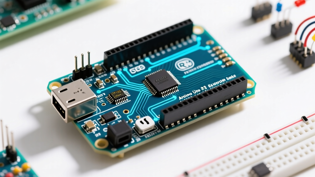
When first learning microcontroller development, the Arduino IDE provides a forgiving abstraction layer. Functions like digitalWrite() and analogRead() shield beginners from the complexities of hardware registers. However, when programming with Arduino Uno for demanding applications—such as high-frequency signal generation, precise motor control, or low-power battery operation—this abstraction becomes a severe bottleneck. In 2026, while the newer Uno R4 Minima (based on the Renesas RA4M1) dominates the market at around $20, the classic Uno R3 featuring the 8-bit Microchip ATmega328P remains a staple for legacy integrations and ultra-low-cost clones (often under $6).
This feature deep dive strips away the Arduino core library to expose the bare metal of the ATmega328P. We will explore direct port manipulation, hardware timer configuration, and advanced memory management techniques that are essential for professional-grade firmware development.
Direct Port Manipulation: Eliminating the digitalWrite() Penalty
The standard digitalWrite(pin, value) function is notoriously slow. Under the hood, it performs pin-to-port mapping, validates PWM timers, and executes multiple conditional branches. On a 16 MHz ATmega328P, digitalWrite() consumes approximately 50 to 60 clock cycles, taking about 3.5 microseconds to execute. If you are bit-banging a high-speed protocol like WS2812B addressable LEDs or driving a multiplexed LED matrix, this latency introduces visible flickering and timing violations.
Understanding DDRx, PORTx, and PINx Registers
The ATmega328P groups its I/O pins into three ports: B, C, and D. Each port is controlled by three 8-bit registers:
- DDRx (Data Direction Register): Configures pins as inputs (0) or outputs (1).
- PORTx (Port Register): Sets the output state (HIGH/LOW) or enables internal pull-up resistors for inputs.
- PINx (Port Input Pins): Reads the current logical state of the pins.
Bitwise Operations in Practice
To manipulate a single pin without affecting the others on the same port, you must use bitwise operators. For example, to set Pin 13 (which maps to PORTB, bit 5) as an output and drive it HIGH:
// Set PB5 (Pin 13) as OUTPUT
DDRB |= (1 << DDB5);

// Drive PB5 HIGH
PORTB |= (1 << PORTB5);

// Drive PB5 LOW
PORTB &= ~(1 << PORTB5);

// Toggle PB5
PINB |= (1 << PINB5);
By writing directly to the PORTB register, the microcontroller executes the instruction in exactly 2 clock cycles (125 nanoseconds). This represents a 28x speed increase over the standard Arduino abstraction.
Mastering Hardware Timers and Interrupts
Relying on delay() or millis() polling loops is an anti-pattern in professional embedded systems. The ATmega328P features three hardware timers: Timer0 (8-bit), Timer1 (16-bit), and Timer2 (8-bit). Note that the Arduino core library hijacks Timer0 for the millis() and delay() functions, so altering its prescaler will break standard timing functions. For custom precision timing, we utilize Timer1.
Configuring Timer1 for CTC Mode
Clear Timer on Compare Match (CTC) mode allows Timer1 to trigger an interrupt at a highly precise interval. Let's configure Timer1 to trigger an interrupt exactly every 1 millisecond (1000 Hz) to create a non-blocking real-time clock.
The formula for the Output Compare Register (OCR1A) value is:
OCR1A = (Clock_Speed / (Prescaler * Target_Frequency)) - 1
For a 16 MHz clock, a prescaler of 64, and a 1000 Hz target frequency:
OCR1A = (16,000,000 / (64 * 1000)) - 1 = 249
void setup() {
  // Disable global interrupts during setup
  cli();

  // Reset Timer1 control registers
  TCCR1A = 0;
  TCCR1B = 0;

  // Set compare match register for 1ms increments
  OCR1A = 249;

  // Turn on CTC mode (WGM12 bit in TCCR1B)
  TCCR1B |= (1 << WGM12);

  // Set CS11 and CS10 bits for 64 prescaler
  TCCR1B |= (1 << CS11) | (1 << CS10);

  // Enable timer compare interrupt
  TIMSK1 |= (1 << OCIE1A);

  // Re-enable global interrupts
  sei();
}

ISR(TIMER1_COMPA_vect) {
  // This code executes exactly every 1.000 ms
  // Keep this ISR as short as possible (e.g., set a flag)
}
This approach guarantees deterministic execution timing, which is critical when programming with Arduino Uno for closed-loop PID control systems or digital filtering.
Memory Architecture and PROGMEM Optimization
The ATmega328P possesses a Harvard architecture with strictly segregated memory spaces: 32 KB of Flash (program memory), 2 KB of SRAM (volatile data), and 1 KB of EEPROM (non-volatile data). The most common point of failure for intermediate developers is SRAM exhaustion, leading to stack collisions and unpredictable reboots.
Offloading Static Data with PROGMEM
Storing large constant arrays—such as sine wave lookup tables for DAC generation or large string literals for an LCD display—directly in your code consumes precious SRAM, as the C compiler copies Flash data into SRAM at boot. According to the official Arduino PROGMEM documentation, you must explicitly instruct the compiler to leave the data in Flash.
#include <avr/pgmspace.h>

// Store 256-byte sine wave lookup table in Flash memory
const uint8_t sine_wave[256] PROGMEM = {
  128, 131, 134, 137, 140, 143, 146, 149, 152, 155, 158, 161, 164, 167, 170, 173
  // ... remaining 240 values omitted for brevity
};

void loop() {
  // Read directly from Flash using pgm_read_byte
  uint8_t value = pgm_read_byte(&sine_wave[i]);
  analogWrite(9, value);
}
EEPROM Wear Leveling Strategies
The 1 KB EEPROM is rated for approximately 100,000 write cycles. If your firmware logs sensor data or saves user settings on every loop iteration, you will destroy the EEPROM cells within days. Implementing a basic wear-leveling algorithm—where the firmware tracks an index pointer and writes to the next available byte, wrapping around at the 1024 boundary—distributes the wear evenly across the memory, extending the lifespan of the chip by orders of magnitude.
Performance Comparison: Abstraction vs. Bare Metal
To illustrate the tangible benefits of register-level programming with Arduino Uno, review the benchmark data below. These metrics were captured using an oscilloscope on a standard 16 MHz Uno R3 clone.
| Operation | Arduino Core Function | Direct Register Equivalent | Execution Time | Flash Overhead |
|---|---|---|---|---|
| Set Pin HIGH | digitalWrite(8, HIGH) |
PORTB |= (1<<PB0) |
3.5 µs vs 0.125 µs | ~120 bytes vs 4 bytes |
| Read Pin State | digitalRead(8) |
(PINB & (1<<PB0)) |
3.2 µs vs 0.125 µs | ~100 bytes vs 4 bytes |
| Analog Read | analogRead(A0) |
Custom ADC Register Config | 104 µs vs 13 µs (High Speed) | ~350 bytes vs 20 bytes |
| Attach Interrupt | attachInterrupt() |
Direct EIMSK / EICRA Config | N/A (Setup overhead) | ~400 bytes vs 12 bytes |
Real-World Failure Modes and the Watchdog Timer
When deploying an Uno in an unmonitored, remote environment (e.g., an off-grid weather station), firmware lockups caused by I2C bus contention, pointer errors, or electromagnetic interference (EMI) are inevitable. The standard Arduino framework does not enable the hardware Watchdog Timer (WDT) by default.
The WDT is an independent internal clock that will force a hardware reset if it is not periodically "pet" (reset) by your firmware. Configuring the WDT to trigger a reset after 2 seconds of unresponsiveness ensures your deployment recovers autonomously from fatal exceptions.
#include <avr/wdt.h>

void setup() {
  // Enable Watchdog Timer with a 2.0 second timeout
  wdt_enable(WDTO_2S);
}

void loop() {
  // Your main application logic
  read_sensors();
  transmit_data();

  // Pet the watchdog. If loop hangs, WDT resets the MCU.
  wdt_reset();
}
Warning: Never enable the WDT during development without a corresponding wdt_disable() or wdt_reset() in your setup/loop. A misconfigured WDT will cause an infinite boot-loop, requiring you to burn a fresh bootloader via an external ISP programmer to recover the board.
Summary: Choosing the Right Approach
There is no universal mandate to abandon the Arduino core library. For prototyping, low-speed sensor polling, and educational projects, digitalWrite() and delay() remain perfectly adequate. However, as your project scales in complexity, mastering direct hardware register manipulation, leveraging 16-bit timers for deterministic interrupts, and optimizing memory via PROGMEM transitions your skillset from hobbyist to embedded systems engineer. For comprehensive schematic and pinout references, always consult the official Arduino Uno R3 hardware documentation before bridging physical ports.