
Introduction to Embedded Prototyping
Learning how to program an Arduino Uno is the rite of passage for every electronics hobbyist, engineering student, and IoT developer. Whether you are building a simple automated plant waterer or a complex robotic arm, the Uno remains the most reliable microcontroller development board on the market. In 2026, the ecosystem has matured significantly, with the introduction of the ARM-based Uno R4 sitting alongside the classic AVR-based Uno R3. This guide will walk you through the exact hardware selection, software configuration, circuit wiring, and C++ coding required to get your first external LED blinking, while avoiding the most common beginner pitfalls.
Hardware Selection: Uno R3 vs. Uno R4 Minima
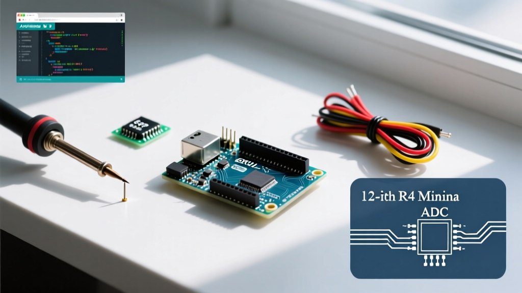
Before writing a single line of code, you need to understand the board on your desk. The market is currently split between the legacy ATmega328P boards and the modern Renesas RA4M1 boards. Both are fully supported by the Arduino ecosystem, but they have distinct hardware profiles.
| Feature | Classic Uno R3 (and Clones) | Modern Uno R4 Minima |
|---|---|---|
| Microcontroller | ATmega328P (8-bit AVR) | Renesas RA4M1 (32-bit ARM Cortex-M4) |
| Clock Speed | 16 MHz | 48 MHz |
| Flash Memory | 32 KB | 256 KB |
| SRAM | 2 KB | 32 KB |
| DAC (Digital to Analog) | None | 12-bit DAC |
| Typical Price (2026) | $12 - $18 (Clones) / $27 (Genuine) | $22 - $28 (Genuine) |
Expert Recommendation: If you are strictly following legacy tutorials or need 5V logic levels for older sensors, the classic Uno R3 (or a high-quality clone) is still perfectly viable. However, for new projects requiring floating-point math, higher memory, or HID (Human Interface Device) capabilities, the Uno R4 Minima is the superior choice and costs roughly the same as a genuine R3.
Software Setup: Configuring Arduino IDE 2.x
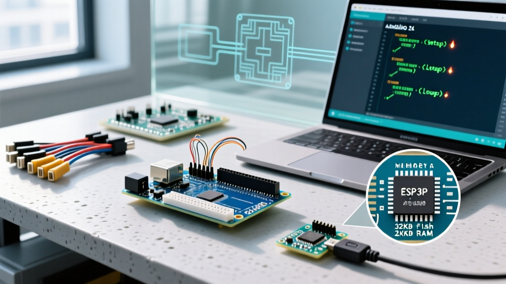
The Arduino IDE has evolved from a basic text editor into a robust development environment. As of 2026, Arduino IDE 2.3+ is the standard, featuring autocomplete, real-time error linting, and an integrated serial plotter.
Step-by-Step Installation
- Download the IDE: Navigate to the official Arduino Software Page and download the installer for your operating system (Windows, macOS, or Linux).
- Install CH340 Drivers (Clone Boards Only): If you purchased a $15 clone Uno R3, it likely uses a CH340G USB-to-serial chip instead of the genuine ATmega16U2. Windows 11 and macOS usually fetch this driver automatically via Windows Update or system extensions. If your board isn't recognized, you must manually install the CH340 driver from the manufacturer's repository.
- Connect the Board: Use a data-capable USB cable (USB-B to USB-A for R3, USB-C for R4). Many beginners fail here because they use 'charge-only' cables scavenged from old electronics, which lack the internal data wires required for serial communication.
- Select Board and Port: In the IDE, go to Tools > Board and select your specific model. Then, go to Tools > Port and select the active COM port (Windows) or /dev/cu.usbmodem port (macOS).
Wiring Your First External Circuit
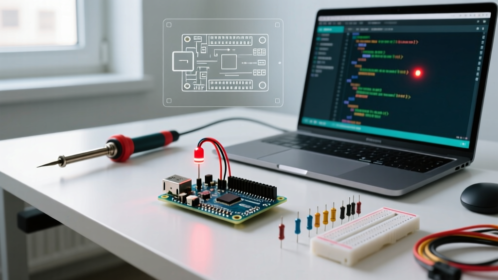
While the Uno has a built-in LED on Pin 13, learning to wire an external component on a breadboard is crucial for understanding microcontroller I/O limits. We will wire a standard 5mm red LED.
The Math Behind the Resistor
Never connect an LED directly to a microcontroller pin without a current-limiting resistor. Doing so will draw excessive current, potentially destroying the LED and the Uno's ATmega328P I/O pin (which has an absolute maximum rating of 40mA per pin, and a recommended limit of 20mA).
Ohm's Law Calculation:
V_source = 5V (Uno output)
V_LED = 2.0V (Typical forward voltage for a red LED)
I_target = 15mA (0.015A - a safe, bright current)
R = (V_source - V_LED) / I_target
R = (5 - 2) / 0.015 = 200 Ohms.
The nearest standard E12 resistor value is 220 Ohms. Using a 220Ω resistor ensures the LED shines brightly while keeping the current draw well within the microcontroller's safe operating area.
Physical Wiring Steps
- Insert the 220Ω resistor into the breadboard. Connect one leg to Pin 13 on the Arduino using a jumper wire.
- Connect the other leg of the resistor to the Anode (the longer leg) of the 5mm LED.
- Connect the Cathode (the shorter leg, flat side of the bulb) to the breadboard's ground rail.
- Run a jumper wire from the breadboard's ground rail to the GND pin on the Arduino.
Writing the Code: Anatomy of a Sketch
Arduino code, known as a 'sketch', is written in a simplified dialect of C++. Every sketch requires two core functions: setup() which runs once on boot, and loop() which runs continuously.
// Define the pin connected to the LED
const int LED_PIN = 13;

void setup() {
  // Initialize the digital pin as an output.
  // Pin 13 has an LED connected on most Arduino boards.
  pinMode(LED_PIN, OUTPUT);

  // Initialize serial communication for debugging
  Serial.begin(9600);
  Serial.println("System Initialized. Starting Blink Sequence.");
}

void loop() {
  digitalWrite(LED_PIN, HIGH);  // Turn the LED on (HIGH is 5V)
  delay(1000);                  // Wait for 1000 milliseconds (1 second)

  digitalWrite(LED_PIN, LOW);   // Turn the LED off (LOW is 0V)
  delay(1000);                  // Wait for a second
}
Uploading the Sketch
Click the Upload button (the right-facing arrow in the top left corner). The IDE will compile the C++ code into AVR/ARM machine code via the GCC compiler, then use the avrdude or bossac bootloader tool to flash the binary over the USB serial connection. The onboard 'TX' and 'RX' LEDs will flicker rapidly during this process.
Troubleshooting Common Upload Errors
When learning how to program an Arduino Uno, you will inevitably encounter upload errors. Here is how to diagnose the most frequent issues based on real-world failure modes.
1. The 'avrdude: stk500_getsync() attempt 10 of 10' Error
This is the most notorious error in the Arduino ecosystem. It means the IDE cannot establish a serial handshake with the bootloader on the microcontroller.
- Cause A (Wrong Port): You selected a phantom COM port. Unplug the Arduino, check the Tools > Port menu, plug it back in, and select the newly appeared port.
- Cause B (Charge-Only Cable): Swap your USB cable. If the TX/RX lights never flash when you plug it in, the cable lacks data lines.
- Cause C (Wrong Board Selected): If you are using an Uno R4 but selected 'Uno R3' in the IDE, the bootloader protocol will mismatch, causing a sync timeout.
2. Port is Grayed Out or Missing
If the Port menu is entirely grayed out, your operating system does not see the USB device. On Windows, open the Device Manager and look under 'Ports (COM & LPT)' or 'Other Devices'. If you see an 'Unknown Device' with a yellow triangle, you are missing the CH340 or FTDI drivers for your specific clone board. For macOS users, ensure you have granted the Arduino IDE permission to access USB accessories in System Settings > Privacy & Security.
3. 'Not a Typo' Compilation Errors
C++ is strictly case-sensitive and requires exact syntax. A missing semicolon at the end of digitalWrite(LED_PIN, HIGH) will cause the compiler to fail. Always check the black console window at the bottom of the IDE; it will provide the exact line number where the syntax violation occurred.
Next Steps and Expanding Your Skills
Congratulations, you have successfully configured your hardware, wired a safe external circuit, and uploaded your first C++ firmware. The blinking LED is the 'Hello World' of embedded systems. To continue your journey, explore the official Arduino starting guide for deeper dives into the language.
Recommended Next Projects:
- Potentiometer Fading: Use
analogRead()to read a 10kΩ potentiometer andanalogWrite()(PWM) to fade the LED smoothly. - Serial Monitor Interaction: Send characters from your PC keyboard to the Arduino to toggle the LED on and off remotely.
- Sensor Integration: Wire a DHT22 temperature and humidity sensor using a 4.7kΩ pull-up resistor and the Adafruit DHT library.
By mastering these foundational concepts, you transition from simply copying code to actively engineering robust electronic systems.