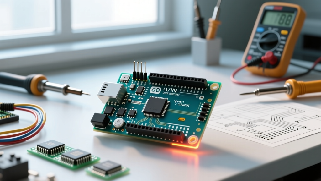

Even in 2026, with the Renesas-based Uno R4 dominating new retail shelves, the classic ATmega328P-based Uno Rev3 remains the most cloned, repaired, and referenced development board in engineering labs worldwide. Whether you are designing a custom shield, troubleshooting a dead board, or creating a standalone microcontroller circuit, understanding the schematic diagram of Arduino Uno Rev3 is a mandatory skill. This deep dive bypasses basic pinout tutorials and dissects the actual component-level engineering, power routing, and communication protocols defined in the official EagleCAD and Altium design files.
The Heartbeat: ATmega328P-PU Clock and Reset Circuits
At the center of the schematic sits the ATmega328P-PU, a 28-pin DIP microcontroller. While the digital and analog I/O pins are straightforward, the supporting passive components on the schematic dictate the board's stability.
The 16MHz Crystal Oscillator Network
The main clock is driven by a 16MHz quartz crystal (Y1) connected to pins PB6 (XTAL1) and PB7 (XTAL2). The schematic specifies two 22pF load capacitors (C4 and C5) tied to ground. This specific value is not arbitrary; it accounts for the crystal's specified load capacitance (typically 18pF to 22pF) plus the estimated 2-5pF of stray parasitic capacitance from the PCB traces. If you are cloning this circuit for a custom PCB, omitting these capacitors or using incorrect values will result in clock drift, causing serial baud rate mismatches and millis() timing errors.
The Auto-Reset Mechanism
One of the most elegant features on the schematic is the auto-reset circuit. The PC6 (RESET) pin is pulled high to 5V via a 10kΩ resistor (R3). However, to allow the Arduino IDE to automatically reset the board before uploading code, a 100nF capacitor (C1) is placed in series between the RESET pin and the DTR (Data Terminal Ready) line from the USB-to-serial IC. When the PC opens the serial port, the DTR line drops low, and the 100nF capacitor momentarily pulls the RESET pin low, triggering a hardware reset without requiring a physical button press.
Power Architecture: From Barrel Jack to 5V Rail
The power section of the schematic diagram of Arduino Uno is where most beginner designs fail and where most cloned boards cut corners. The Rev3 schematic implements a robust, multi-layered power management system.
- Reverse Polarity Protection: Power from the 2.1mm barrel jack first passes through an M7 diode (D1). This is a 1A, 1000V surface-mount diode that prevents catastrophic failure if a user accidentally connects a negative-center power supply.
- The 5V LDO Regulator: The board utilizes the ON Semiconductor NCP1117ST50T3G, a 500mA low-dropout (LDO) regulator in a SOT-223 package. The schematic shows a 100nF input capacitor and a 10µF tantalum output capacitor to ensure transient stability.
- USB Overcurrent Protection: The 5V from the USB port is routed through a Bourns MF-MSMF050-2 resettable PTC polyfuse. This limits current to 500mA, protecting your computer's USB host controller if your Arduino project shorts out.
Thermal Dissipation Warning: The NCP1117 is a linear regulator, meaning it burns excess voltage as heat. If you supply 12V via the barrel jack and draw 300mA from the 5V pin, the regulator must dissipate (12V - 5V) × 0.3A = 2.1 Watts. The SOT-223 package will exceed 100°C and trigger its internal thermal shutdown. For high-current projects, always bypass the onboard regulator and supply 5V directly to the 5V header pin.
USB-to-Serial Routing: The ATmega16U2 Sub-System
Older Arduino boards used the FT232RL or ATmega8U2 for USB communication. The Rev3 schematic upgrades this to the ATmega16U2-MU, a dedicated 32-pin QFN microcontroller. This chip acts as a USB-to-Serial bridge, running a custom LUFA-based firmware.
The schematic reveals a secondary 16MHz crystal (Y2) and its own 22pF load capacitors specifically for the 16U2. More importantly, the schematic includes a 6-pin ICSP header dedicated solely to the 16U2. If you accidentally brick the USB firmware (or want to reprogram the Uno to act as a native HID keyboard or MIDI device), you can use this header and the HWB (Hardware Boot) pin—routed to GND via a solder jumper pad on the bottom of the board—to force the 16U2 into Atmel FLIP DFU (Device Firmware Upgrade) mode.
Schematic-to-Physical Pin Mapping Matrix
When reading the schematic, the net names do not always match the silkscreen on the physical headers. Use this matrix to bridge the gap between the schematic diagram and your physical multimeter probes.
| Schematic Net Name | Physical Header Pin | ATmega328P Port | Hardware Function / Notes |
|---|---|---|---|
| RX0 / PD0 | Digital 0 (RX) | PD0 | UART Receive (Shared with USB Serial) |
| TX0 / PD1 | Digital 1 (TX) | PD1 | UART Transmit (Shared with USB Serial) |
| SS / PB2 | Digital 10 | PB2 | SPI Slave Select (Critical for Ethernet/SD shields) |
| MOSI / PB3 | Digital 11 | PB3 | SPI Master Out Slave In |
| MISO / PB4 | Digital 12 | PB4 | SPI Master In Slave Out |
| SCK / PB5 | Digital 13 | PB5 | SPI Clock / Onboard LED |
| ADC6 | Not Broken Out | ADC6 | Analog Input Only (No digital I/O capability) |
Schematic-Driven Troubleshooting: 3 Common Failure Modes
By cross-referencing the schematic with a digital multimeter (DMM), you can diagnose dead boards in minutes rather than guessing.
1. The 'Dead 5V Rail' Short
Symptom: The board gets hot near the USB port or the LDO, and the 5V pin reads 0V. Schematic Fix: Set your DMM to continuity mode. Probe the 5V header pin against GND. If it reads near 0 ohms, you have a dead short. This is usually caused by a failed NCP1117 LDO or a shorted decoupling capacitor on a connected shield. Desolder the 5V pin header and test again to isolate whether the short is on the Arduino or the shield.
2. USB Enumeration Failure
Symptom: The computer does not recognize the device, but the 5V and 3.3V rails are present. Schematic Fix: The USB D+ and D- lines pass through 22Ω series resistors (R1 and R2) before reaching the ATmega16U2. These resistors are prone to physical damage if the USB cable is yanked. Probe across R1 and R2 for continuity. If open, bridge them with a tiny solder blob or replace with 0603 22Ω resistors.
3. Manual Reset Required for Uploads
Symptom: The IDE throws an 'avrdude: stk500_recv(): programmer is not responding' error unless you physically press the reset button at the exact moment the upload begins. Schematic Fix: The auto-reset capacitor (C1, 100nF) has failed or the trace from the 16U2 DTR pin to C1 is severed. Verify continuity from the 16U2 pin 13 (PD7) to the anode of C1. If the trace is intact, replace the 100nF capacitor.
Accessing the Official Design Files
To perform your own modifications or verify component footprints, always refer to the primary source. You can download the official EagleCAD schematic and PCB layout files directly from the Arduino Uno Rev3 Hardware Documentation page. Studying these native design files provides invaluable insights into trace width calculations, ground plane stitching, and component placement strategies that you can apply to your own custom PCB designs in KiCad or Altium.