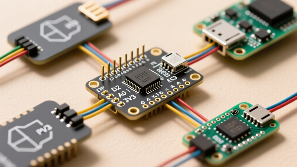

The Case for Migrating from the Classic Nano
For over a decade, the ATmega328P-based Arduino Nano has been the undisputed king of the breadboard. Its 0.6-inch DIP footprint and straightforward 5V logic made it the default choice for rapid prototyping. However, as we navigate the embedded landscape in 2026, the limitations of an 8-bit, 16MHz microcontroller with 32KB of Flash memory are increasingly restrictive. Modern edge-ML, high-speed ADC sampling, and native Wi-Fi/BLE requirements demand a platform migration.
Upgrading to 32-bit powerhouses like the dual-core ESP32-S3 (typically $8.50 for a DevKitC-1) or the Raspberry Pi Pico W ($6.00) offers exponential performance gains. But this transition is rarely plug-and-play. A deep understanding of the Arduino Nano pin configuration is the critical first step to avoid silicon damage, logic errors, and firmware bugs during migration.
Deconstructing the Arduino Nano Pin Configuration
Before mapping pins to a new architecture, we must audit the legacy Nano's I/O topology. The classic Nano (Rev3) features 30 pins arranged in two 15-pin headers. While it shares the same ATmega328P silicon as the Uno, its physical footprint and specific pin multiplexing harbor several traps for the uninitiated.
⚠️ The A6/A7 Analog Trap: Unlike the Arduino Uno, which routes all analog pins through a multiplexer that allows digital I/O, pins A6 and A7 on the classic Arduino Nano are strictly hardwired to the ADC. They lack digital pull-up/pull-down resistors and cannot executedigitalWrite()ordigitalRead(). When migrating code to the ESP32 or Pico, you must reassign these specific sensor lines to true multiplexed GPIOs on the new board.
Power Delivery and the VIN Pin Trap
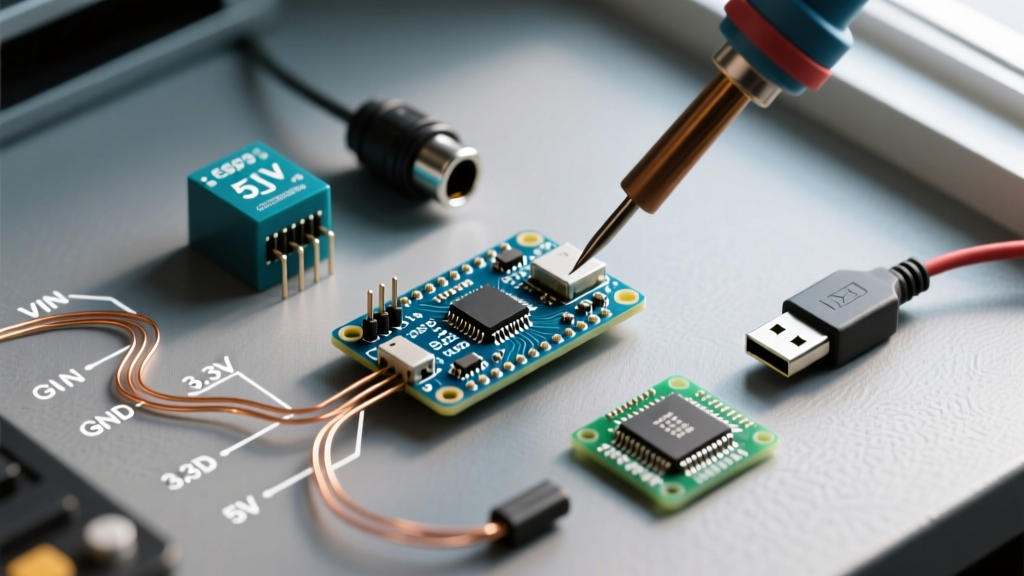
The Nano's VIN pin is tied to an onboard linear regulator (typically an NCP1117 or similar), expecting 7V to 12V input. In contrast, modern ESP32-S3 and Pico dev boards utilize highly efficient buck-boost converters optimized for 5V USB-C VBUS input. Feeding 12V into the VIN equivalent of a modern dev board will instantly destroy the PCB traces or the PMIC. Always migrate external power supplies to the dedicated 5V or 3.3V regulated pins on your target board.
Cross-Platform Pin Mapping Matrix
When translating your breadboard layout, use this reference matrix. This table maps the core functions of the Arduino Nano pin configuration to the most popular 2026 migration targets: the ESP32-S3 DevKitC-1 and the Raspberry Pi Pico W.
| Nano Pin | Primary Function | ESP32-S3 DevKitC-1 Equivalent | Raspberry Pi Pico W Equivalent | Migration Notes |
|---|---|---|---|---|
| D0 (RX) | Hardware UART RX | GPIO44 (RX0) | GP1 (UART0 RX) | ESP32-S3 uses matrix routing; Pico uses programmable I/O blocks. |
| D1 (TX) | Hardware UART TX | GPIO43 (TX0) | GP0 (UART0 TX) | Ensure 3.3V logic levels if connecting to 5V USB-TTL adapters. |
| D2 | INT0 (External Interrupt) | GPIO2 | GP2 | ESP32 supports interrupts on any GPIO; Pico supports on GP0-GP22. |
| A4 | I2C SDA | GPIO8 | GP4 | Pico requires Wire.setSDA(4) in setup if not using default I2C0. |
| A5 | I2C SCL | GPIO9 | GP5 | Verify pull-up resistor voltage rails (see Hardware Gotchas below). |
| D9, D10 | Hardware PWM / SPI SS | GPIO38, GPIO39 | GP6, GP7 | ESP32 uses LEDC peripheral for PWM; Pico uses hardware PWM slices. |
| A0 - A5 | 10-bit ADC (0-5V) | GPIO1 - GPIO7 | GP26 - GP29 (ADC0-3) | Scale firmware to handle 12-bit resolution and 3.3V reference limits. |
Critical Hardware Migration Gotchas
Mapping the Arduino Nano pin configuration on paper is only half the battle. The physical electrical characteristics of the ATmega328P differ vastly from modern ARM and Xtensa architectures. Ignoring these hardware realities will lead to erratic sensor readings or catastrophic component failure.
1. Logic Level Shifting (The 5V vs 3.3V Divide)
The classic Nano operates at 5V logic. A HIGH signal outputs ~4.8V. Both the ESP32-S3 and RP2040 (Pico) are strictly 3.3V devices. Feeding a 5V Nano output directly into an ESP32 GPIO will cause long-term silicon degradation or immediate latch-up.
- Unidirectional Lines (e.g., Nano to ESP32 SPI): Use a simple voltage divider (10kΩ and 22kΩ resistors) or a dedicated non-inverting buffer IC like the NXP 74HC4050 (74HC4050 Datasheet), which costs roughly $0.80 per unit.
- Bidirectional Lines (e.g., I2C, 1-Wire): You must use a dedicated MOSFET-based level shifter like the Texas Instruments TXS0108E or the PCA9515A I2C isolator. Do not rely on resistor dividers for bidirectional open-drain protocols.
2. ADC Non-Linearity and Reference Voltages
The Nano's 10-bit ADC is relatively linear from 0V to 5V. Modern platforms introduce complexity:
- ESP32-S3 ADC: The 12-bit ADC is notoriously non-linear at the voltage rails. According to the Espressif ESP32-S3 Datasheet, the usable linear range with 11dB attenuation is roughly 0.15V to 3.1V. If your Nano project relied on reading exactly 0.05V or 4.9V, you must add an external op-amp circuit or use an external I2C ADC like the ADS1115.
- Raspberry Pi Pico ADC: The RP2040 features a 12-bit SAR ADC, but its accuracy is entirely dependent on the
ADC_VREFpin. If powered via a noisy USB hub, your analog readings will fluctuate wildly. For precision migration, feed a clean 3.3V LDO directly into the Pico'sADC_VREFpin (Pin 35).
3. I2C Pull-Up Resistor Conflicts
The Arduino Nano pin configuration for I2C (A4/A5) relies on 5V pull-ups, either internal or external on the sensor breakout board. When migrating to a 3.3V ESP32, those 5V pull-ups will backfeed current into the ESP32's GPIO protection diodes. Before migrating, inspect your sensor modules. If they feature hardcoded 4.7kΩ pull-ups tied to a 5V VIN trace, you must physically cut the trace and re-solder the pull-ups to the 3.3V rail, or use an I2C level-shifting breakout board.
Step-by-Step Firmware Adaptation
Once your hardware is safely interfaced, the firmware requires structural changes to accommodate the new silicon.
- Audit PWM Implementations: The Nano uses
analogWrite()with a default frequency of 490Hz (980Hz on D5/D6). The ESP32-S3 does not supportanalogWrite()natively in the same way; you must use the LEDC API (ledcAttach()andledcWrite()in the 2026 Arduino Core) to define frequency and resolution. The Pico supportsanalogWrite()but allows hardware PWM frequency tuning viaanalogWriteFreq(). - Update Analog Resolution Calls: The Nano returns 0-1023. To maintain math compatibility in your legacy code without rewriting algorithms, insert
analogReadResolution(10)in your Pico setup. For the ESP32, you will need to map the 12-bit values (0-4095) down to 10-bit using themap()function or bit-shifting (val >> 2). - Refactor Interrupt Syntax: The Nano uses fixed hardware interrupts (INT0 on D2, INT1 on D3). Modern ARM/RISC-V boards support interrupts on almost any pin. Ensure your code uses the portable
attachInterrupt(digitalPinToInterrupt(pin), ISR, mode)syntax rather than hardcoded AVR register manipulation (e.g.,EICRAorEIMSK), which will fail to compile on 32-bit targets.
Frequently Asked Questions (FAQ)
Can I use the 5V pin on the ESP32 to power my Nano shields?
Yes, but with severe caveats. The 5V pin on an ESP32 DevKit or Pico is tied directly to the USB VBUS line. It bypasses the onboard voltage regulator. If your legacy Nano shield draws more than 400mA (leaving 100mA margin for the ESP32's Wi-Fi radio spikes), you will brownout the USB port or melt the micro-USB/USB-C trace. For high-current 5V shields, use an external buck converter fed from a dedicated 12V/5V wall supply.
Why is my migrated I2C OLED display failing to initialize on the Pico?
This is the most common migration failure. The Arduino Nano Hardware Documentation confirms A4/A5 as default I2C. However, the Raspberry Pi Pico's default I2C0 pins are GP4 (SDA) and GP5 (SCL). If you wired your display to GP0/GP1 (which map to UART), the Wire.begin() command will silently fail. You must either rewire to GP4/GP5 or explicitly declare Wire.setSDA(0) and Wire.setSCL(1) before initialization.
Is it worth migrating to the Arduino Nano RP2040 Connect instead?
If your project strictly requires the physical 0.6-inch Nano footprint and 5V tolerance, the Nano RP2040 Connect ($28.50) or the Nano ESP32 ($22.00) are excellent bridge boards. They retain the exact Arduino Nano pin configuration footprint but upgrade the silicon to 32-bit architectures. However, be aware that the Nano ESP32 operates at 3.3V logic despite the 5V power pin, meaning you still need to address the logic-level shifting gotchas outlined above if your legacy shield expects 5V data signals.