
The Architecture Shift: RA4M1 Meets ESP32-S3
The release of the Arduino Uno R4 WiFi marked a definitive end to the ATmega328P era for flagship Arduino boards. Retailing at approximately $27.50 in 2026, the Uno R4 WiFi pairs a 32-bit Renesas RA4M1 Arm Cortex-M4 microcontroller (clocked at 48MHz) with an ESP32-S3 WROOM-1 module for Wi-Fi and Bluetooth Low Energy (BLE) connectivity. This dual-core architecture provides a massive upgrade in processing power—boasting 256KB Flash and 32KB SRAM—but it also introduces a completely new hardware topology.
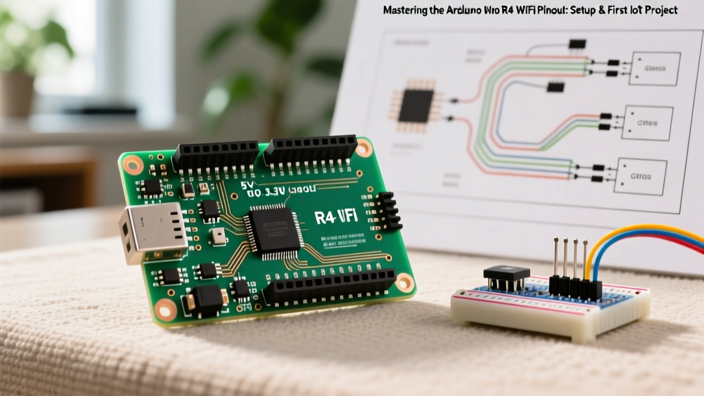
For makers and engineers transitioning from the classic Uno R3, understanding the Arduino Uno R4 WiFi pinout is critical. The board maintains the physical R3 footprint for shield compatibility, but the underlying electrical routing, voltage logic, and peripheral headers have evolved significantly. In this guide, we will dissect the pinout, clarify the voltage domains, and walk through a complete first-project setup to get your IoT sensor dashboard online.
Decoding the Arduino Uno R4 WiFi Pinout
While the digital and analog headers mirror the classic Uno layout, the R4 WiFi introduces several dedicated hardware features that require specific pin mappings. Below is a structural comparison highlighting the hardware differences you must account for in your schematics.
| Feature / Pin | Classic Uno R3 (ATmega328P) | Uno R4 WiFi (RA4M1 + ESP32-S3) |
|---|---|---|
| Main Processor | 8-bit AVR @ 16MHz | 32-bit Arm Cortex-M4 @ 48MHz |
| Wireless Module | None | ESP32-S3 (Wi-Fi 4 / BLE 5.0) |
| VUSB Pin | Not present | Present (Bypasses 5V regulator) |
| I2C / Qwiic | Shared on A4/A5 | Dedicated SDA/SCL + Qwiic Connector |
| Debugging | None (requires bootloader) | 6-pin SWD Header |
| LED Matrix | None | 12x8 Red LED Matrix (Internally wired) |
Critical Pin Differences and New Additions
- The VUSB Pin: Located on the digital header, this new pin provides direct access to the USB-C VBUS (5V). It bypasses the onboard 5V regulator and its protective diode. Use this when powering high-current USB peripherals (like LED strips or cellular modems) directly from the USB-C port, but be aware it is limited to the current rating of your USB cable and host port (typically 1A to 3A).
- Dedicated I2C & Qwiic: The R4 WiFi separates the hardware I2C lines from analog pins A4 and A5. The SDA and SCL pins on the digital header are now independent, and the board includes a 4-pin Qwiic/Stemma QT connector for solderless 3.3V I2C sensor integration.
- SWD Debug Header: The 6-pin Serial Wire Debug (SWD) header allows you to attach hardware debuggers like the J-Link or ST-Link for step-through debugging of the RA4M1, a feature previously reserved for professional Arm development boards.
Voltage Logic: Navigating 5V and 3.3V Domains
One of the most common failure modes when migrating to the R4 WiFi is mismanaging voltage logic. The Renesas RA4M1 is natively a 3.3V microcontroller. However, to maintain backward compatibility with legacy 5V shields, Arduino integrated bidirectional level shifters on the digital I/O pins (D0-D13) and the dedicated SDA/SCL header pins.
Expert Warning: While the digital pins are 5V tolerant via level shifters, the analog pins (A0-A5) and the Qwiic connector operate strictly at 3.3V. Feeding a 5V signal into A0 will permanently damage the RA4M1's ADC circuitry. Always use a voltage divider or logic level converter for analog sensors operating at 5V.
Step-by-Step Environment Setup
Before writing code, you must configure the Arduino IDE to handle the dual-chip architecture. The ESP32-S3 acts as a network bridge, communicating with the RA4M1 via an internal UART bus.
- Update the IDE: Ensure you are using Arduino IDE 2.3.2 or newer (as of early 2026) to support the latest board definitions and serial port multiplexing.
- Install the Core: Open the Boards Manager, search for Arduino UNO R4 Boards, and install the latest version (v1.2.0+).
- Port Selection: When you plug the board via USB-C, your OS may detect two serial ports. Always select the port labeled USB Serial (RA4M1) for uploading sketches. The second port is the ESP32-S3 bridge debug port.
- Firmware Check: Run the FirmwareUpdater example sketch to ensure the ESP32-S3 WROOM module has the latest network stack firmware. Outdated bridge firmware is the leading cause of Wi-Fi connection timeouts.
First Project: Wi-Fi Connected I2C Sensor Dashboard
For our first project, we will leverage the Qwiic connector, the onboard 12x8 LED matrix, and the ESP32-S3 to build a local IoT dashboard. We will read temperature data from a BME280 sensor, display a dynamic thermal icon on the matrix, and serve the data via a local web page.
Hardware Wiring
Because we are using the Qwiic ecosystem, wiring is foolproof. Connect a SparkFun BME280 Qwiic breakout to the Uno R4 WiFi's Qwiic connector using a standard 4-pin I2C cable. No pull-up resistors are needed, as the breakout board and the Uno R4 both feature onboard 4.7kΩ pull-ups on the 3.3V I2C bus.
The Code Implementation
You will need to install the Adafruit BME280 Library via the Library Manager. The code below utilizes the native WiFiS3 and Arduino_LED_Matrix libraries included in the R4 core.
#include
#include
#include
#include
// Replace with your network credentials
const char* ssid = "YOUR_SSID";
const char* password = "YOUR_PASSWORD";
WiFiServer server(80);
Adafruit_BME280 bme;
ArduinoLEDMatrix matrix;
// 12x8 Matrix Frame: Thermometer Icon
const uint32_t thermo_icon[] = {
0x00000000, 0x00000000, 0x00000000,
0x00111110, 0x01000001, 0x01000001,
0x01011001, 0x01011001, 0x01011001,
0x00111110, 0x00011000, 0x00000000
};
void setup() {
Serial.begin(115200);
matrix.begin();
if (!bme.begin(0x77)) {
Serial.println("BME280 not found on Qwiic bus!");
while (1);
}
Serial.print("Connecting to Wi-Fi...");
WiFi.begin(ssid, password);
while (WiFi.status() != WL_CONNECTED) {
delay(500);
Serial.print(".");
}
Serial.println("\nConnected! IP:");
Serial.println(WiFi.localIP());
server.begin();
}
void loop() {
matrix.loadFrame(thermo_icon);
float temp = bme.readTemperature();
WiFiClient client = server.available();
if (client) {
String response = "HTTP/1.1 200 OK\r\nContent-Type: text/html\r\n\r\n";
response += "Uno R4 IoT Dashboard
";
response += "Temperature: " + String(temp) + " C
";
client.print(response);
client.stop();
}
delay(100);
}
Troubleshooting Common R4 WiFi Edge Cases
Even with a flawless pinout understanding, the dual-chip nature of the R4 WiFi introduces specific edge cases that trip up developers. Refer to the Arduino Uno R4 WiFi Documentation for deep-dive schematics, but keep these practical tips in mind:
- ESP32 Bridge Crashes: If the ESP32-S3 module crashes during heavy TCP traffic, the RA4M1 will continue running, but
WiFi.status()will freeze. Implement a watchdog timer or periodically ping the gateway to trigger a software reset of the network bridge via theWiFi.end()andWiFi.begin()sequence. - USB-C Power Dropouts: When powering the 12x8 LED matrix at maximum brightness while simultaneously transmitting Wi-Fi data, the board can draw upwards of 450mA. If connected to an unpowered USB 2.0 hub, the voltage may sag below 4.5V, causing the ESP32-S3 to brownout and disconnect. Always use a dedicated 5V/2A USB-C wall adapter for IoT deployments.
- Analog Reference Drift: By default, the analog reference (AREF) is tied to the 3.3V rail. If you require higher precision for analog sensors, you can pass
analogReference(AR_INTERNAL2V5)to utilize the RA4M1's internal 2.5V reference, as detailed in the Renesas RA4M1 Hardware Manual.
By mastering the physical routing and voltage domains of the Arduino Uno R4 WiFi pinout, you unlock the ability to build robust, high-speed IoT devices that bridge the gap between hobbyist accessibility and professional Arm-based engineering. For further exploration of the WiFiS3 library capabilities, consult the official WiFiS3 library reference to implement secure TLS/SSL web clients in your next iteration.