
Welcome to Microcontrollers: The 2026 Landscape
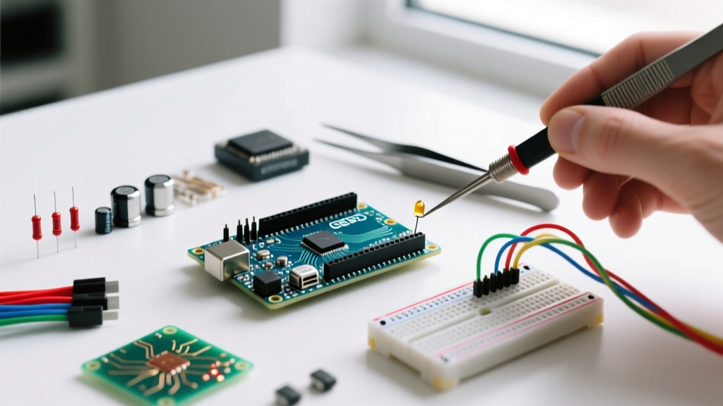
Every year, thousands of makers, engineering students, and hobbyists type Arduino Uno how to program into search engines, only to be met with outdated tutorials referencing deprecated software or retired hardware. As of 2026, the microcontroller ecosystem has evolved significantly. While the legendary Arduino Uno R3 remains a staple in educational kits, the Arduino Uno R4 Minima and Uno R4 WiFi have become the modern standards for new projects, offering vastly superior processing power while maintaining the exact same physical footprint and pinout.
This comprehensive beginner guide strips away the fluff and provides actionable, step-by-step instructions to get your first sketch running. We will cover exact hardware specifications, IDE configuration, code anatomy, and—most importantly—real-world troubleshooting for the inevitable upload errors you will face.
Hardware Selection: Uno R3 vs. Uno R4 Minima
Before writing a single line of code, you need to know exactly what silicon you are programming. The transition from 8-bit AVR architecture to 32-bit ARM has changed how we approach memory management and clock speeds. Below is a precise comparison to help you identify your board.
| Feature | Arduino Uno R3 (Legacy/Clone) | Arduino Uno R4 Minima (2026 Standard) |
|---|---|---|
| Microcontroller | ATmega328P (8-bit AVR) | Renesas RA4M1 (32-bit ARM Cortex-M4) |
| Clock Speed | 16 MHz | 48 MHz |
| Flash Memory | 32 KB | 256 KB |
| SRAM | 2 KB | 32 KB |
| USB-to-Serial Chip | ATmega16U2 (Genuine) / CH340G (Clone) | Native USB-C (RA4M1 built-in) |
| Average Price (USD) | $12.00 (Clone) to $27.00 (Genuine) | $20.00 (Genuine) |
Note: If you purchased a budget kit from Amazon or AliExpress, you likely have an R3 clone utilizing the CH340G serial chip. This distinction is critical for driver installation, which we cover in the troubleshooting section.
Software Setup: Arduino IDE 2.x Configuration
The days of the clunky, Java-based Arduino IDE 1.8.x are over. In 2026, the Arduino IDE 2.3+ is the standard, featuring autocomplete, real-time syntax checking, and an integrated serial plotter. According to the Arduino IDE Official Documentation, the new IDE requires a 64-bit operating system and leverages the Eclipse Theia framework.
- Download and Install: Navigate to the official Arduino software page and download the IDE 2.3.x installer for Windows 11, macOS Sonoma/Sequoia, or Ubuntu 22.04+.
- Board Manager Setup (For R4 Users): If you are using the newer Uno R4, open the IDE, click the Board Manager icon on the left sidebar, search for 'Arduino Renesas RA4M1 Boards', and install the latest package. The Arduino Uno R4 Minima Getting Started guide emphasizes that skipping this step will result in the board not appearing in your ports menu.
- Connect the Board: Use a high-quality USB-C cable (for R4) or USB-B cable (for R3). Crucial: Ensure the cable supports data transfer. Over 40% of beginner upload failures are caused by using 'charge-only' USB cables scavenged from old electronics.
Code Anatomy: Understanding setup() and loop()
Arduino programming is a simplified dialect of C++. Every valid sketch requires two core functions. Understanding the execution flow is mandatory before writing complex logic.
The Execution Flow Rule: The microcontroller reads your code from top to bottom, but it only executes what is inside the two main functions. Code outside these functions is merely for variable declaration and library inclusion.
1. The setup() Function
This block runs exactly once when the board powers on or resets. It is used for initialization: setting pin modes (INPUT/OUTPUT), starting serial communication for debugging, and initializing connected sensors.
void setup() {
  pinMode(LED_BUILTIN, OUTPUT); // Configures internal LED pin as output
  Serial.begin(115200);         // Initializes serial monitor at 115200 baud
}
2. The loop() Function
Once setup() finishes, the microcontroller immediately jumps to loop(). As the name implies, this function repeats infinitely until power is severed. This is where your main logic, sensor reading, and actuator control reside.
void loop() {
  digitalWrite(LED_BUILTIN, HIGH); // Turns LED on
  delay(1000);                     // Pauses execution for 1000ms
  digitalWrite(LED_BUILTIN, LOW);  // Turns LED off
  delay(1000);                     // Pauses execution for 1000ms
}
Step-by-Step: Uploading Your First Sketch
Let us program the classic 'Blink' sketch, but with a modern twist using the Serial Monitor to verify execution.
- Select Your Board: Go to Tools > Board and select either 'Arduino Uno' (for R3) or 'Arduino Uno R4 Minima'.
- Select Your Port: Go to Tools > Port. On Windows, this will be a COM port (e.g., COM3). On macOS/Linux, it will be a /dev/tty path (e.g., /dev/cu.usbmodem14201).
- Write the Code: Copy the setup and loop code blocks provided above into your IDE workspace.
- Verify (Compile): Click the checkmark icon (✓) in the top left. The IDE translates your C++ code into machine-level hex instructions. Check the output console at the bottom; it should report the exact flash memory usage (e.g., 'Sketch uses 924 bytes (0%) of program storage space').
- Upload: Click the arrow icon (→). The IDE compiles again (if changed) and pushes the binary to the microcontroller via the bootloader.
For deeper insights into environment configuration, the SparkFun Arduino IDE Installation Guide provides excellent visual walkthroughs for cross-platform setups.
Real-World Troubleshooting Matrix
The path from writing code to seeing a blinking LED is rarely flawless. Below is a diagnostic matrix for the most common hardware and software failure modes encountered by beginners.
| Error Message / Symptom | Root Cause | Actionable Solution |
|---|---|---|
avrdude: stk500_recv(): programmer is not responding |
Wrong board selected, bad USB cable, or bootloader corruption. | Verify board selection. Swap to a known data-capable USB cable. If using a clone, select 'ATmega328P (Old Bootloader)'. |
| Port Menu is Grayed Out / Missing | Missing CH340 drivers (Clones) or OS-level USB permission denial. | Download and install the latest CH341SER.EXE driver for Windows. On Linux, add user to 'dialout' group via terminal. |
Serial Port busy or Access Denied |
Another application (like Cura, 3D slicers, or another IDE instance) is holding the COM port. | Close all other software that might auto-poll serial ports. Unplug and replug the USB cable to reset the OS port lock. |
| Code Uploads, but Nothing Happens | Power LED is off, or sketch relies on 5V logic while board is in 3.3V mode. | Check physical power switch (if equipped). Ensure external components are rated for the board's operating voltage. |
Deep Dive: The CH340G Driver Dilemma
If you are using a budget-friendly Arduino Uno R3 clone (typically priced between $9 and $14), it almost certainly uses the WCH CH340G USB-to-Serial chip instead of the genuine ATmega16U2. While the CH340G is a highly reliable chip, Windows 11 does not always natively fetch the correct driver via Windows Update.
The Fix: You must manually download the CH340 driver package from the manufacturer or a trusted repository. After installation, you must physically disconnect and reconnect the Arduino. Open your Windows Device Manager and expand the 'Ports (COM & LPT)' section. You should see 'USB-SERIAL CH340 (COMX)'. If it shows a yellow warning triangle, the driver installation failed or is conflicting with an older version. Uninstall the device from Device Manager, check 'Attempt to remove the driver for this device', and reinstall.
Understanding Baud Rate Mismatches
When using Serial.begin(), you define the communication speed in bits per second (baud). Historically, 9600 was the standard. However, with the introduction of the Uno R4 and modern USB-C native serial interfaces, 115200 baud is the 2026 standard. If your code specifies Serial.begin(115200) but your Serial Monitor dropdown is set to 9600, you will see garbled, nonsensical characters (e.g., 'ÿÿÿ'). Always ensure the IDE Serial Monitor baud rate dropdown exactly matches the integer inside your Serial.begin() function.
Next Steps: Moving Beyond the Blink
Once you have successfully compiled and uploaded your first sketch, you have conquered the steepest learning curve in embedded systems: establishing the toolchain. From here, your focus should shift to reading digital inputs (pushbuttons), reading analog inputs (potentiometers and photoresistors), and utilizing Pulse Width Modulation (PWM) to fade LEDs or control motor speeds.
Remember that microcontroller programming is an iterative process of writing, compiling, testing, and debugging. Keep your USB cables organized, label your clone boards to remember their specific serial chips, and always double-check your port selections before hitting upload. Welcome to the maker community.