
The High-Speed Stepper Ecosystem: Why Pin Selection Matters
When engineering multi-axis CNC routers, high-speed 3D printers, or precision robotics, the standard AccelStepper library often becomes a severe bottleneck on 8-bit AVR microcontrollers. Relying on software-based interrupts, standard libraries typically max out around 4,000 steps per second per motor before introducing catastrophic timing jitter. Enter FastAccelStepper, a highly optimized library that offloads step-pulse generation to the microcontroller's hardware timers, pushing step rates well beyond 20,000 steps per second with zero CPU jitter.
However, this massive performance gain comes with strict hardware constraints. Understanding the FastAccelStepper Arduino Mega supported pins is not just a matter of picking random digital I/O; it requires a deep understanding of the ATmega2560 hardware timer ecosystem. If you wire your stepper drivers to the wrong pins, the library will either fail to compile, fallback to sluggish software stepping, or silently break other core Arduino functions.
ATmega2560 Hardware Timer Architecture
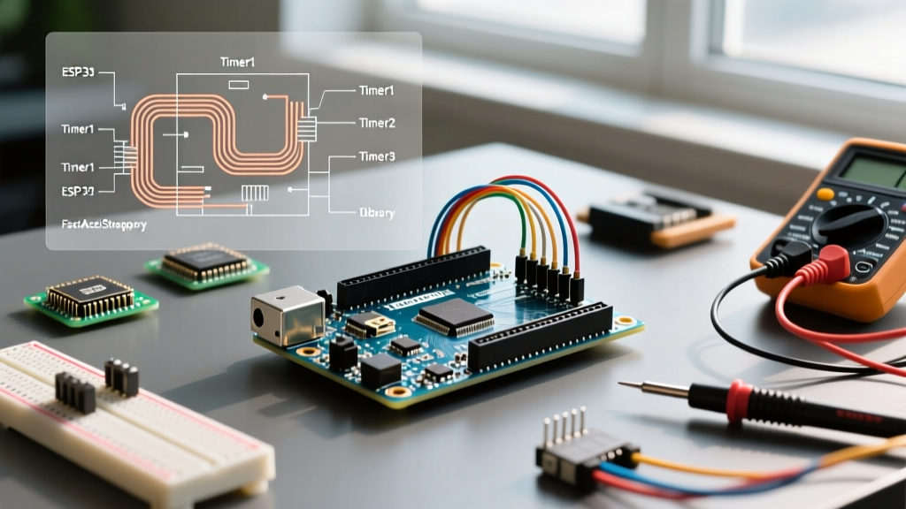
To generate perfectly timed, jitter-free square waves for stepper motor STEP pins, FastAccelStepper utilizes the 16-bit hardware timers on the Microchip ATmega2560. The Arduino Mega 2560 features six hardware timers, but they are not created equal:
- Timer 0 (8-bit): Reserved for core Arduino functions like
millis(),delay(), andmicros(). FastAccelStepper cannot use this timer. - Timer 1 (16-bit): Technically capable, but heavily contested by the standard
Servo.hlibrary and core PWM functions. - Timer 2 (8-bit): Unsupported by the library's 16-bit step-generation logic.
- Timers 3, 4, and 5 (16-bit): The primary workhorses for FastAccelStepper on the Mega ecosystem.
Because the library uses the hardware Output Compare (OC) toggle feature, only the specific physical pins wired to these 16-bit timers can be used as STEP pins.
FastAccelStepper Arduino Mega Supported Pins Matrix
Below is the definitive mapping of supported STEP pins based on the FastAccelStepper GitHub Repository and the Arduino Mega 2560 Official Documentation. You may use up to 9 independent hardware-accelerated steppers on a single Mega by utilizing Timers 3, 4, and 5.
| Hardware Timer | Output Compare Channel | Arduino Mega Digital Pin | Ecosystem Notes & Conflicts |
|---|---|---|---|
| Timer 3 | OC3A | Pin 5 | Safe for dedicated STEP use. Disables PWM on Pin 5. |
| Timer 3 | OC3B | Pin 2 | Safe. Note: Pin 2 is also an external interrupt (INT4). |
| Timer 3 | OC3C | Pin 3 | Safe. Disables PWM on Pin 3. |
| Timer 4 | OC4A | Pin 6 | Safe for dedicated STEP use. Disables PWM on Pin 6. |
| Timer 4 | OC4B | Pin 7 | Safe. Disables PWM on Pin 7. |
| Timer 4 | OC4C | Pin 8 | Safe. Disables PWM on Pin 8. |
| Timer 5 | OC5A | Pin 46 | Safe. Disables PWM on Pin 46. |
| Timer 5 | OC5B | Pin 45 | Safe. Disables PWM on Pin 45. |
| Timer 5 | OC5C | Pin 44 | Safe. Disables PWM on Pin 44. |
| Timer 1 | OC1A / OC1B | Pins 11, 12 | AVOID: Breaks Servo.h and core analogWrite functions. |
The Golden Rule: Step Pins vs. Direction and Enable Pins
A common point of confusion for makers integrating the FastAccelStepper library is the assumption that all motor control pins must be on the supported hardware timer list. This is incorrect and leads to unnecessary wiring nightmares.
Ecosystem Insight: Only the STEP pin requires a hardware-timer-mapped OC pin. The DIRECTION and ENABLE pins are toggled via standard software GPIO operations and can be assigned to any available digital or analog pin on the Arduino Mega.
For example, if you are wiring a 4-axis CNC shield to an Arduino Mega, you would wire your STEP signals to Pins 5, 2, 3, and 6 (using Timers 3 and 4). Your DIRECTION pins could safely be routed to Pins 22, 23, 24, and 25, and your ENABLE pin to Pin 26. This hybrid approach preserves the Mega's vast GPIO ecosystem while strictly adhering to the library's hardware acceleration requirements.
Navigating Ecosystem Conflicts and Edge Cases
When operating at the intersection of high-speed motion control and peripheral management, timer collisions are the most frequent cause of project failure. Here is how to navigate the ATmega2560 ecosystem safely:
1. The Servo Library Collision
The standard Arduino Servo.h library monopolizes Timer 1 and, if you run out of channels, will cascade into Timer 3, 4, and 5. If your project requires both high-speed steppers and RC servos (e.g., for a robotic arm end-effector), you must use an alternative servo library like VarSpeedServo or hardware PCA9685 PWM drivers via I2C to keep Timers 3, 4, and 5 exclusively reserved for FastAccelStepper.
2. AnalogWrite (PWM) Destruction
Because FastAccelStepper reconfigures the Timer Control Registers (TCCR) to output precise, continuous square waves, the standard analogWrite() function will permanently fail on any pin associated with a hijacked timer. If your project requires dimming LEDs or controlling DC spindle motors via PWM, ensure you route those PWM requirements to Timer 2 (Pins 9, 10) or use a dedicated digital-to-analog converter (DAC).
Signal Integrity at 20kHz+ Step Rates
Pushing an Arduino Mega to output 20,000 to 30,000 step pulses per second exposes the physical limitations of breadboard wiring and cheap jumper cables. At these frequencies, the STEP signal is essentially a high-frequency RF transmission. Capacitive coupling between adjacent wires can cause 'ghost steps', leading to lost position accuracy in CNC applications.
Stepper Driver Compatibility
Not all stepper drivers handle the fast rise-and-fall times of hardware-accelerated 5V logic equally well.
- Trinamic TMC2209 / TMC2226: Excellent ecosystem partners. However, ensure the
VCC_IOpin on the TMC breakout board is tied to the Mega's 5V rail, not 3.3V, to guarantee the logic high threshold is reliably met at high frequencies. - Texas Instruments DRV8825: Highly tolerant of the Mega's 5V logic, but requires careful tuning of the current limit potentiometer to prevent thermal shutdown during high-acceleration ramps.
- Allegro A4988: Generally reliable, but older clone boards often suffer from optocoupler propagation delays. If using isolated CNC shields, ensure the optocouplers are rated for at least 50kHz switching speeds; standard PC817 optocouplers will severely bottleneck your FastAccelStepper max speeds.
Implementation Best Practices
When initializing your code, always explicitly define your supported pins and verify your timer allocation. A standard initialization block for a 3-axis setup looks like this:
#include 'FastAccelStepper.h'

FastAccelStepperEngine engine = FastAccelStepperEngine();
FastAccelStepper *stepperX = NULL;
FastAccelStepper *stepperY = NULL;

void setup() {
  engine.init();
  // Pin 5 (Timer 3), Dir Pin 22, Enable Pin 23
  stepperX = engine.stepperConnectToPin(5);
  stepperX->setDirectionPin(22);
  stepperX->setEnablePin(23);

  // Pin 6 (Timer 4), Dir Pin 24, Enable Pin 25
  stepperY = engine.stepperConnectToPin(6);
  stepperY->setDirectionPin(24);
  stepperY->setEnablePin(25);
}
Summary: Mastering the Mega Ecosystem
The Arduino Mega 2560 remains a highly cost-effective platform for multi-axis motion control, with genuine boards hovering around $45 and high-quality clones available for $15 to $20. By strictly adhering to the FastAccelStepper Arduino Mega supported pins matrix and respecting the underlying 16-bit timer architecture, you unlock industrial-grade motion profiles on hobbyist hardware. Plan your pinouts before you wire, isolate your high-frequency STEP lines, and let the hardware timers handle the heavy lifting.