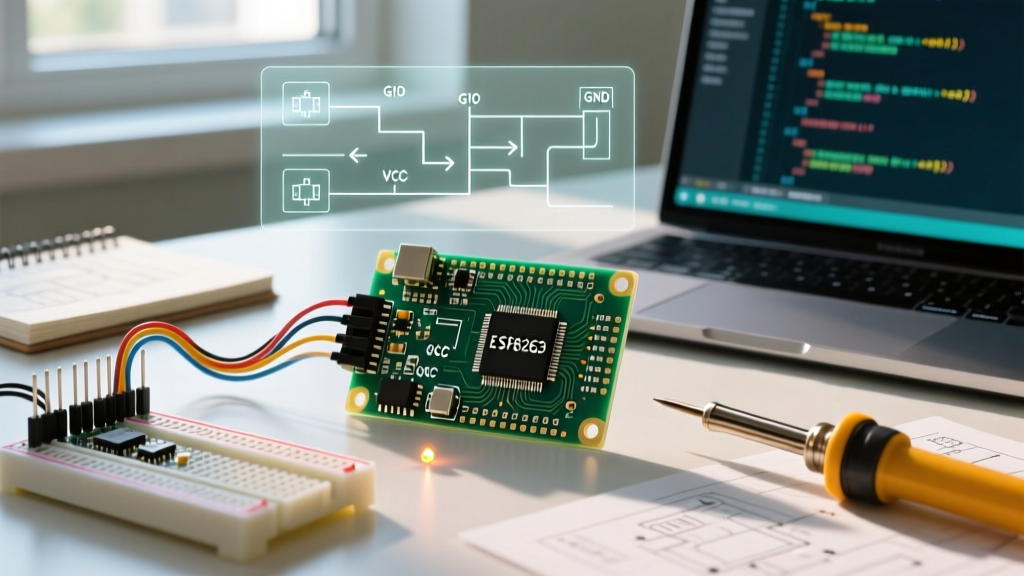

Why the ESP8266 Remains a 2026 Prototyping Staple
Despite the rapid adoption of the ESP32-S3 and Raspberry Pi Pico W, the original ESP8266 remains an undisputed champion for budget-conscious IoT projects in 2026. With a single-core 80 MHz Tensilica processor, integrated 802.11 b/g/n Wi-Fi, and a price point that hovers around $4 per development board, it is the ultimate entry point for wireless electronics. However, the hardware is only half the battle. To unlock its potential, you need to bridge the gap between Espressif's native SDK and the maker-friendly ecosystem by mastering the ESP8266 and Arduino IDE integration.
This guide bypasses the generic fluff and dives straight into the exact hardware variants, driver edge cases, and GPIO mapping quirks you need to know to get your first Wi-Fi scan running without pulling your hair out.
Hardware Selection: NodeMCU vs. Wemos D1 Mini vs. ESP-01
Not all ESP8266 boards are created equal. The bare ESP-12F module requires external voltage regulation and pull-up resistors, making it unsuitable for beginners. Instead, you should choose a development board with an integrated USB-to-UART bridge. Here is how the top three options compare in the current market:
| Board Model | USB-UART Chip | Avg. Price (2026) | Best Use Case |
|---|---|---|---|
| NodeMCU v3 (LoLin) | CH340G | $4.50 | Breadboarding, ample GPIO pins, beginner default. |
| Wemos D1 Mini | CH340G / CP2104 | $3.80 | Compact projects, stacking shields, space-constrained builds. |
| ESP-01S | None (Requires Adapter) | $2.10 (+ $2 adapter) | Deep sleep sensor nodes, flashing AT firmware, advanced users. |
Expert Tip: Always buy boards with the CP2104 or updated CH340G chips. Avoid boards with the CH340C if you are running older Linux kernels, as driver support can be spotty.
Step-by-Step: Configuring the ESP8266 and Arduino IDE
The native Arduino IDE does not support Espressif chips out of the box. You must install the community-maintained core. According to the official Arduino Board Manager documentation, third-party cores are added via JSON URLs.
Step 1: The USB Driver Trap (Windows 11 Edge Case)
Before opening the IDE, plug your NodeMCU into your PC. If your Device Manager shows an 'Unknown Device' or a USB serial port with a warning triangle, you need the CH340 driver.
CRITICAL 2026 WARNING: Windows 11's 'Core Isolation / Memory Integrity' security feature actively blocks the older v3.4 CH340 drivers commonly found on random blogs. You must download the v3.8+ signed driver directly from the official WCH (Nanjing Qinheng) website, or Windows will silently fail to install it.
Step 2: Adding the Board Manager URL
- Open the Arduino IDE (v2.3 or newer recommended).
- Navigate to File > Preferences (or Arduino IDE > Settings on macOS).
- Locate the 'Additional boards manager URLs' field.
- Paste the official JSON link:
http://arduino.esp8266.com/stable/package_esp8266com_index.json - Click OK.
Step 3: Installing the Core
Open the Boards Manager tab on the left sidebar, search for esp8266, and install the package by 'ESP8266 Community'. As of early 2026, version 3.1.2 is the most stable release. Avoid beta versions unless you specifically need the latest TLS 1.3 patches for MQTT brokers.
Wiring and Your First Upload: The GPIO Mapping Quirk
Let us test the connection with a simple Wi-Fi network scanner. But first, you must understand the most confusing aspect for beginners: GPIO mapping.
The silkscreen on a NodeMCU v3 says 'D4'. However, the ESP8266 Arduino Core GitHub repository maps the physical pin 'D4' to the internal 'GPIO 2'. If you try to use digitalWrite(4, HIGH), you will actually trigger GPIO 4 (labeled D2 on the board), not the onboard LED.
The Wi-Fi Scanner Code
Upload this snippet to verify your ESP8266 and Arduino IDE toolchain is working. Go to Tools > Board and select NodeMCU 1.0 (ESP-12E Module). Set the Upload Speed to 115200 and the CPU Frequency to 80 MHz.
#include

void setup() {
  Serial.begin(115200);
  delay(1000);
  Serial.println('\nScanning for Wi-Fi networks...');

  // Set WiFi to station mode and disconnect from any saved AP
  WiFi.mode(WIFI_STA);
  WiFi.disconnect();
  delay(100);

  int n = WiFi.scanNetworks();
  if (n == 0) {
    Serial.println('No networks found.');
  } else {
    Serial.print(n);
    Serial.println(' networks found.');
    for (int i = 0; i < n; ++i) {
      Serial.printf('%d: %s (%d dBm) %s\n', i + 1, WiFi.SSID(i).c_str(), WiFi.RSSI(i), (WiFi.encryptionType(i) == ENC_TYPE_NONE) ? 'OPEN' : 'ENCRYPTED');
      delay(10);
    }
  }
}

void loop() {
  // Scanner runs once in setup
}
Common Failure Modes & Troubleshooting Matrix
When working with the ESP8266, hardware and software boundaries blur. Here is a diagnostic matrix for the most common errors encountered when linking the ESP8266 and Arduino IDE.
| Error Message / Symptom | Root Cause | Actionable Solution |
|---|---|---|
| 'Failed to connect to ESP8266: Timed out waiting for packet header' | The board is not entering UART bootloader mode. GPIO0 is not being pulled LOW during reset. | Press and hold the 'FLASH' button, tap the 'RST' button, then release 'FLASH'. Alternatively, solder a 10uF capacitor between EN and GND to auto-reset via the DTR line. |
| Random Reboots / Watchdog Resets (Exception 9 or 29) | Power brownout. The ESP8266 draws up to 430mA during RF transmission spikes, exceeding the AMS1117 voltage regulator's thermal limits on cheap clones. | Power the board via the 'Vin' pin using a dedicated 5V 2A buck converter or bench supply. Do not rely on standard laptop USB 2.0 ports (limited to 500mA). |
| 'Board not found' / COM port greyed out | USB cable is 'charge-only' (missing internal D+ and D- data wires), or CH340 driver conflict. | Swap to a verified data-sync USB cable. Check Device Manager for 'USB-SERIAL CH340'. |
| Wi-Fi connects but no HTTP response | Missing yield() or delay() in a tight while() loop, causing the RF stack to starve and disconnect. |
Always include yield(); inside blocking loops to allow the ESP8266 background RF tasks to execute. |
Understanding Boot Mode Constraints
According to Espressif's official hardware design guidelines, the ESP8266 determines its boot mode by sampling specific GPIO pins at the exact moment the EN (CH_PD) pin goes HIGH.
- GPIO 0: Must be HIGH for normal flash execution. If LOW, it enters UART download mode.
- GPIO 2: Must be HIGH (or floating with internal pull-up) for normal boot. Do not wire a relay or heavy load directly to GPIO 2, or the board will fail to boot when power is cycled.
- GPIO 15: Must be LOW for normal boot. If pulled HIGH, it boots from an external SDIO (which is rarely used by hobbyists).
Ignoring these strapping pin requirements is the number one reason why a circuit works perfectly on your desk (where you manually press reset) but fails when deployed in a wall enclosure with an automated smart plug or timer relay.
Next Steps: Moving Beyond the Blink Test
Once you have successfully compiled and uploaded code using the ESP8266 and Arduino IDE, your immediate next step should be exploring Over-The-Air (OTA) updates. By including the ArduinoOTA.h library, you can push new firmware via Wi-Fi without ever unplugging the board from your breadboard or unscrewing it from your project enclosure. This transforms the ESP8266 from a simple learning tool into a highly deployable, professional-grade IoT node.