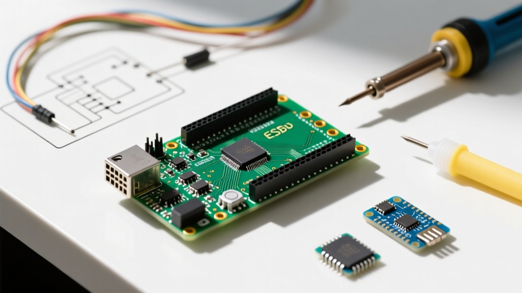
The Paradigm Shift: Ditching the MAX3421E Shield
For years, integrating USB peripherals into microcontroller projects meant pairing an Arduino Mega with a bulky USB Host Shield based on the MAX3421E chip. While functional, this legacy approach introduced severe bottlenecks: high pin overhead (SPI + interrupt lines), significant power draw, and a hard speed limit dictated by the SPI bus rather than the USB protocol itself. As of 2026, the ESP32-S3 USB Host Arduino ecosystem has fully matured, offering native USB 2.0 Full-Speed (12 Mbps) OTG (On-The-Go) capabilities directly on the silicon.
Migrating to the ESP32-S3 eliminates the need for external host controllers, slashing BOM (Bill of Materials) costs and reducing physical footprint. However, native USB Host implementation introduces new hardware and software complexities—specifically regarding VBUS power delivery and TinyUSB stack configuration—that catch many migrating developers off guard.
Migration Matrix: Legacy Shield vs. Native ESP32-S3
Before rewriting your firmware, it is crucial to understand the architectural differences between the old SPI-bridged method and the modern native PHY approach.
| Feature | Arduino Mega + MAX3421E Shield | ESP32-S3 DevKit (Native OTG) |
|---|---|---|
| Approx. Hardware Cost (2026) | $38.00 - $45.00 | $8.00 - $12.00 |
| Bus Speed Limitation | SPI Bottleneck (~8 MHz effective) | USB Full-Speed (12 Mbps native) |
| GPIO Pin Overhead | 6+ Pins (MOSI, MISO, SCK, SS, INT) | 2 Pins (GPIO 19, GPIO 20) |
| Software Stack | USB_Host_Shield_2.0 (Legacy) | TinyUSB via ESP32 Arduino Core v3.x |
| Power Consumption (Idle) | ~85mA (Shield + MCU) | ~22mA (Deep Sleep capable) |
Critical Hardware Wiring: PHY Pinout and the VBUS Trap
The ESP32-S3 integrates the USB PHY internally, mapping the data lines directly to GPIO 19 (D-) and GPIO 20 (D+). Unlike the ESP32-C3 or standard ESP32, the S3 supports both Device and Host modes. However, the most common point of failure during platform migration is misunderstanding VBUS power delivery.
The 5V VBUS Requirement
The ESP32-S3 operates at 3.3V logic. Fortunately, the USB 2.0 standard specifies that D+ and D- signaling occurs at 3.3V, meaning you can connect the data lines directly to your USB-A female receptacle without level shifters. However, USB peripherals (like HID keyboards, mice, or flash drives) require 5V on the VBUS pin to power their internal controllers.
Expert Warning: The VBUS Power Sag
Do not attempt to power a USB peripheral's VBUS line using the 3.3V output pin of the ESP32-S3 DevKit. The onboard AMS1117-3.3 LDO will overheat and trigger thermal shutdown if the peripheral draws more than 100mA. Furthermore, the device will fail to enumerate because it expects 4.75V minimum on VBUS. You must route the 5V pin from the DevKit (sourced from the USB-C programming port or an external 5V supply) directly to the USB-A receptacle's VBUS pin.
Signal Integrity and ESD Protection
If you are migrating from a breadboard prototype to a custom PCB in 2026, adhere to strict USB routing rules. The D+ and D- traces must be routed as a 90-ohm differential pair. Keep trace lengths under 50mm and avoid placing vias on the data lines. Additionally, integrate a USB ESD protection diode array (such as the Nexperia PRTR5V0U2X or TI TPD4E05U06) directly behind the USB-A connector to protect the S3's sensitive internal PHY from hot-plug electrostatic discharge.
Arduino IDE Configuration for Native OTG
With the widespread adoption of the ESP32 Arduino Core v3.x, the underlying USB stack has transitioned to a TinyUSB backend. To enable Host mode, you must configure the IDE tools menu correctly before compiling.
- Board Selection: Choose your specific ESP32-S3 board (e.g., ESP32S3 Dev Module).
- USB Mode: Change this from the default 'Hardware CDC and JTAG' to 'USB-OTG (TinyUSB)'. This is the most critical step; without it, the native port remains locked in Device/JTAG mode.
- USB CDC On Boot: Set to 'Enabled' if you wish to use the native USB port for Serial debugging simultaneously, though note that bandwidth is shared.
- Firmware Partition Scheme: Select 'Huge APP (3MB No OTA/1MB SPIFFS)' to accommodate the TinyUSB host stack and FAT32 filesystem libraries if using mass storage.
Code Implementation: Enumerating a USB HID Device
Below is a streamlined implementation for enumerating a standard USB HID Keyboard using the native USB.h and hidkeyboard.h libraries included in the modern ESP32 Core. This replaces the bloated callback structures required by the old MAX3421E shield libraries.
#include "USB.h"
#include "hidkeyboard.h"

// Instantiate the USB Host and Keyboard objects
USBHost USB_Device;
HIDKeyboard Keyboard(USB_Device);

void setup() {
  // Initialize standard Serial for debug output via UART0
  Serial.begin(115200);
  delay(2000);
  Serial.println("ESP32-S3 USB Host Migration: Awaiting HID Device...");

  // Start the USB Host stack
  USB_Device.begin();
  Keyboard.begin();
}

void loop() {
  // Check if a keypress is available in the buffer
  if (Keyboard.available()) {
    char keyPressed = (char)Keyboard.read();

    // Filter out non-printable control characters for clean Serial output
    if (keyPressed >= 32 && keyPressed <= 126) {
      Serial.print(keyPressed);
    } else if (keyPressed == '\n' || keyPressed == '\r') {
      Serial.println();
    }
  }
}
Troubleshooting Enumeration Failures
When migrating legacy code, developers frequently encounter the "Device Descriptor Request Failed" error. Based on field data from 2026 hardware deployments, here are the primary edge cases and their solutions:
- VBUS Timing Delay: The TinyUSB stack expects VBUS to be stable before initiating enumeration. If your peripheral has large decoupling capacitors, the 5V rail may ramp up too slowly. Add a 200ms delay in your
setup()loop after powering the VBUS MOSFET (if using switched power) before callingUSB_Device.begin(). - Missing Pull-Down Resistors: While the ESP32-S3 handles internal PHY termination, some custom breakout boards omit the required 15k-ohm pull-down resistors on D+ and D- at the host receptacle. Verify your schematic against the ESP32-S3 Technical Reference Manual USB schematic guidelines.
- Hub Back-Powering: If connecting an unpowered USB hub, peripherals may attempt to back-power the ESP32-S3 through the data lines. Always use a powered hub for multi-device enumeration, or implement a hardware VBUS current-limiting IC (like the AP2128) to prevent silicon damage.
- Mass Storage FAT32 Limits: When migrating USB flash drive code, ensure the drive is formatted strictly to FAT32. The ESP32-S3 Arduino FATFS implementation currently struggles with exFAT allocation tables larger than 32GB, leading to silent mount failures.
Conclusion
Migrating to an ESP32-S3 USB Host Arduino architecture is a definitive upgrade for modern embedded systems. By eliminating the SPI bottleneck, reducing BOM costs by over 60%, and leveraging the TinyUSB stack, developers can build highly responsive, low-power USB data loggers and HID interfaces. Success hinges on respecting the 5V VBUS power requirements and correctly configuring the Core v3.x IDE parameters.