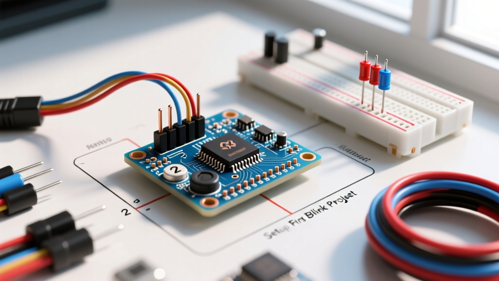

Decoding the Arduino Nano Pins Layout
The Arduino Nano remains one of the most versatile microcontroller boards for compact prototyping. Whether you are using a genuine board (around $22-$25) or a third-party clone ($4-$6), understanding the exact Arduino Nano pins layout is critical to avoiding fried components and logic errors. Measuring just 45mm x 18mm, the Nano packs the same ATmega328P processing power as the Uno but in a breadboard-friendly DIP-30 footprint.
Unlike larger boards, the Nano's physical width (18mm) means it straddles the center dip of a standard 830-point solderless breadboard. This leaves exactly one row of tie-points exposed on either side for jumper wires. If your breadboard has integrated power rails that are too close to the center, the Nano's headers may overlap, requiring you to solder extended pin headers or use a Nano shield expansion board.
Comprehensive Pinout Matrix
| Pin Category | Pin Numbers | Voltage / Function | Crucial Limitations & Edge Cases |
|---|---|---|---|
| Power | 5V, 3V3, GND, VIN | 5V/3.3V Out, 7-12V In | 5V pin max ~500mA via USB, but limit to ~200mA via VIN to prevent LDO thermal shutdown. |
| Digital I/O | D0-D13 | 5V Logic, 20mA max | D0 (RX) and D1 (TX) are shared with hardware Serial. Using them for I/O will break USB serial monitoring. |
| Analog In | A0-A7 | 0-5V ADC (10-bit) | Critical: A6 and A7 are strictly analog INPUTS. They lack digital output buffers and internal pull-up resistors. |
| Comms | A4 (SDA), A5 (SCL) | I2C Bus | Shared with analog inputs. Pull-up resistors (4.7kΩ) are required for stable I2C communication. |
| PWM | D3, D5, D6, D9, D10, D11 | ~490Hz (D5/D6 at ~980Hz) | Marked with a '~' on the silkscreen. Essential for motor speed control and LED fading. |
Power Architecture and Failure Modes
Powering the Nano incorrectly is the fastest way to destroy the board. According to the Arduino Nano Official Documentation, the board features three primary power pathways, each with distinct failure modes:
- USB Mini-B (or USB-C on modern clones): Provides 5V directly to the 5V rail through a polyfuse rated at 500mA. This is the safest way to power the board during setup.
- The 5V Pin: Bypasses the onboard voltage regulator entirely. You must supply a regulated 5V source here. Feeding 6V or higher into this pin will instantly fry the ATmega328P chip.
- The VIN Pin: Connects to the onboard linear voltage regulator (typically an AMS1117-5.0 on clones). While the Microchip ATmega328P Datasheet indicates the chip can handle up to 6V on VCC, the Nano's VIN accepts 7-12V. However, linear regulators dissipate excess voltage as heat. If you supply 12V to VIN and draw 150mA from the 5V pin, the regulator must dissipate 1.05W of heat. Without a heatsink, this will trigger thermal shutdown within seconds.
Expert Tip: If your project requires more than 200mA of continuous 5V current (e.g., driving multiple servos or high-brightness LED strips), do not power it through the Nano's onboard regulator. Use a dedicated external 5V buck converter (like an LM2596 module) wired directly to the Nano's 5V and GND pins.
IDE Setup and the 'Old Bootloader' Trap
Before wiring your first project, you must establish a stable serial connection. Download the latest IDE from the Arduino IDE 2.x Download Portal. In 2026, Windows 11 natively recognizes the FT232RL and ATmega16U2 chips used on genuine boards. However, if you purchased a budget clone, it likely uses the CH340 USB-to-serial chip.
Step-by-Step Connection
- Plug the Nano into your USB port. Open Device Manager (Windows) or System Report (macOS) to verify the COM port assignment.
- In the Arduino IDE, navigate to Tools > Board and select Arduino Nano.
- Under Tools > Processor, you will face the infamous bootloader fork. Select ATmega328P for genuine boards and high-end clones. If you receive an avrdude: stk500_getsync() error upon uploading, switch this setting to ATmega328P (Old Bootloader). Most $5 clones ship with the older 2KB bootloader to save flash space.
- Select the correct COM port under Tools > Port.
First Project: Potentiometer-Controlled PWM Fade
To validate your Arduino Nano pins layout understanding, we will build an interactive circuit that reads an analog voltage and outputs a PWM signal. This tests the ADC (Analog-to-Digital Converter), the PWM generator, and the serial monitor simultaneously.
Hardware Requirements
- 1x Arduino Nano (soldered with extended headers for breadboard use)
- 1x 10kΩ Linear Potentiometer
- 1x Standard 5mm LED
- 1x 220Ω Current-Limiting Resistor
- Breadboard and male-to-male jumper wires
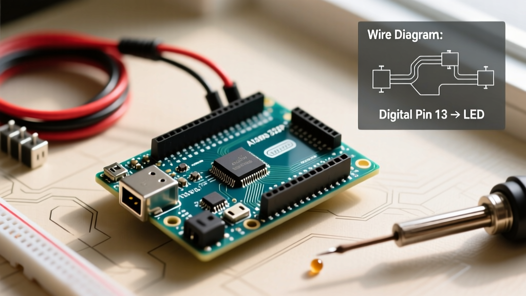
Wiring Diagram Instructions
Follow these exact connections to avoid short circuits:
- Potentiometer: Connect the left pin to 5V, the right pin to GND, and the middle wiper pin to A0.
- LED: Connect the anode (long leg) to D9 (a PWM-capable pin) through the 220Ω resistor. Connect the cathode (short leg) to GND.
The Firmware Code
Upload the following sketch. It maps the 10-bit analog reading (0-1023) to an 8-bit PWM duty cycle (0-255).
// Potentiometer PWM Fade - Arduino Nano Setup Tutorial
const int potPin = A0;  // Analog input pin
const int ledPin = 9;   // PWM output pin

void setup() {
  pinMode(ledPin, OUTPUT);
  Serial.begin(9600); // Initialize serial for debugging
}

void loop() {
  // Read the analog voltage (0 to 5V maps to 0 to 1023)
  int sensorValue = analogRead(potPin);

  // Map the 10-bit value to an 8-bit PWM value
  int pwmValue = map(sensorValue, 0, 1023, 0, 255);

  // Apply the PWM signal to the LED
  analogWrite(ledPin, pwmValue);

  // Print to serial monitor to verify ADC linearity
  Serial.print('ADC: '); Serial.print(sensorValue);
  Serial.print(' | PWM: '); Serial.println(pwmValue);

  delay(15); // Short delay for ADC stability
}
Troubleshooting Common Nano Edge Cases
Even with a perfect understanding of the Arduino Nano pins layout, physical hardware quirks can cause failures. Here is how to diagnose the most common issues:
1. The 'Not in Sync' Upload Error
If the IDE throws avrdude: stk500_getsync() attempt 10 of 10: not in sync, the computer cannot handshake with the bootloader. Fix: First, verify you selected 'Old Bootloader' if using a clone. Second, ensure nothing is connected to D0 (RX) and D1 (TX) during the upload process, as external circuits can corrupt the serial handshake. Disconnect sensors from D0/D1, upload, and reconnect.
2. Erratic Analog Readings (Floating Pins)
If your serial monitor shows wild fluctuations on A0 even when the potentiometer is stationary, you may have a 'floating' ground or breadboard contact issue. Fix: The Nano's GND pins are located on opposite ends of the board. Ensure you are using a thick jumper wire for the main ground bus, and verify that the breadboard's metal clips haven't been permanently stretched out by previous thick component leads.
3. I2C Sensor Failing to Initialize
When connecting OLED displays or BME280 sensors to A4 (SDA) and A5 (SCL), the bus may hang. Fix: The ATmega328P's internal pull-ups are roughly 30kΩ to 50kΩ, which is too weak for high-speed I2C or long wire runs. Solder external 4.7kΩ pull-up resistors between the SDA/SCL lines and the 5V (or 3.3V, depending on your sensor's logic level) rail.
Mastering the physical and logical constraints of the Nano's pinout transforms it from a simple blinking toy into a robust platform for embedded systems. Always respect the current limits of the GPIO pins, leverage the PWM channels for actuator control, and utilize the dedicated analog inputs for precise sensor telemetry.