
The Architecture of Time: Budget vs Premium Timer Strategies
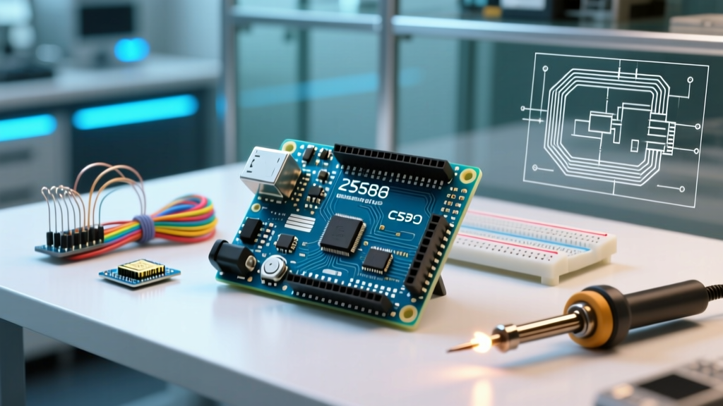
When engineers ask how to use freertos timers with esp32 arduino, they are usually looking for a simple code snippet to blink an LED or debounce a button. However, in professional IoT and industrial control systems, timing is not just about triggering an event; it is about precision, memory management, and interrupt latency. In 2026, the ESP32 ecosystem has matured significantly, splitting into two distinct architectural paradigms: the Budget Approach (FreeRTOS Software Timers on standard ESP32-WROOM modules) and the Premium Approach (Hardware-backed GPTimers integrated with FreeRTOS queues on ESP32-S3 and ESP32-C6 chips).
Understanding the difference between these two methods is critical. A budget software timer might cost you almost zero in terms of code complexity, but it will introduce jitter. A premium hardware timer demands rigorous ISR (Interrupt Service Routine) management but guarantees microsecond-level execution. Let us break down exactly how to implement both, their true costs, and when to deploy them.
Expert Insight: The default FreeRTOS tick rate on ESP32 Arduino is 1000Hz (1ms). Any software timer you create is inherently bottlenecked by this 1ms resolution. If your application requires 50-microsecond precision, software timers will fail you, regardless of how well you write the code.
The Budget Tier: FreeRTOS Software Timers
The budget approach relies entirely on the FreeRTOS Timer Daemon Task. This is a background task created automatically by the ESP32 Arduino core. When you create a software timer, you are simply adding a lightweight struct to a queue that the daemon task monitors.
Resource Cost and Memory Footprint
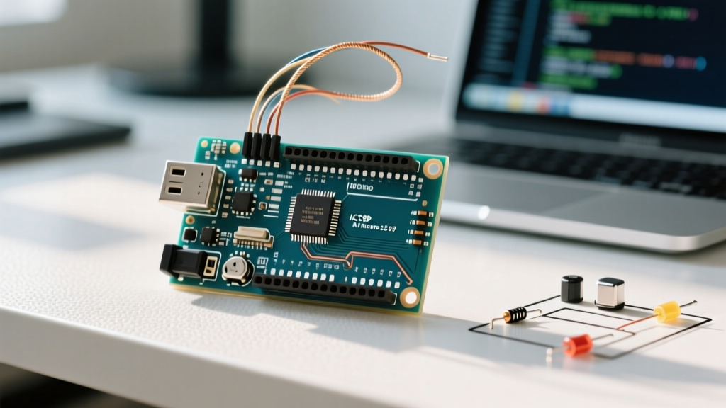
Using standard hardware like the ESP32-WROOM-32E (typically priced around $4.50 to $5.50 per unit in bulk), RAM is a precious commodity. Fortunately, FreeRTOS software timers are incredibly lightweight. Each timer instance consumes approximately 44 bytes of RAM. The heavy lifting is done by the Timer Daemon Task, which requires a dedicated stack defined by configTIMER_TASK_STACK_DEPTH (usually set to 2048 bytes in the ESP32 Arduino environment).
Implementation Workflow
- Define the Callback: Create a void function that accepts a
TimerHandle_tparameter. This function must execute quickly; blocking the daemon task will stall all other software timers. - Instantiate the Timer: Use
xTimerCreate(), passing a text name (for debugging), the period in ticks usingpdMS_TO_TICKS(), the auto-reload boolean, a timer ID, and your callback function. - Activate: Call
xTimerStart()with a block time (e.g.,pdMS_TO_TICKS(10)) to push the start command to the daemon queue.
The Budget Limitation: Jitter and Queue Blockages
Because the daemon task processes commands sequentially via a queue (configured by configTIMER_QUEUE_LENGTH, default 10), a sudden burst of timer expirations can overflow the queue. Furthermore, if your callback function includes a delay() or waits on a slow I2C sensor read, you will block the daemon task, causing catastrophic timing drift across your entire application.
The Premium Tier: Hardware-Backed Timers via FreeRTOS
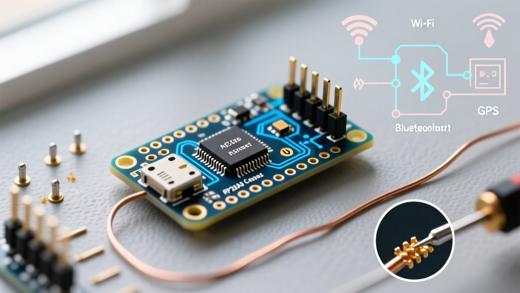
The premium approach abandons the FreeRTOS software timer daemon entirely for the actual timekeeping. Instead, it leverages the silicon-level General Purpose Timers (GPTimer) available on premium chips like the ESP32-S3-WROOM-1 ($8.50 - $11.00) or the RISC-V based ESP32-C6. Here, the hardware peripheral counts clock cycles and fires an interrupt, which then signals a high-priority FreeRTOS task to execute the payload.
Why Pay the Premium?
In industrial motor control, high-frequency sensor polling, or precise PWM phase-shifting, 1ms of jitter is unacceptable. The ESP32-S3 GPTimer can resolve time down to 500 nanoseconds (using an 80MHz APB clock with a prescaler of 1). By decoupling the timekeeping from the FreeRTOS tick rate, you achieve deterministic execution.
Implementation Workflow (ESP-IDF 5.x Paradigm)
Modern ESP32 Arduino core versions (v3.x and above, wrapping ESP-IDF 5.1+) utilize the new GPTimer API rather than the legacy timer_group driver.
- Step 1: Configure the GPTimer: Use
gptimer_new_timer()to allocate a hardware timer handle. Set the clock source toGPTIMER_CLK_SRC_DEFAULTand define your resolution (e.g., 1MHz for 1-microsecond ticks). - Step 2: Register the ISR Callback: Use
gptimer_register_event_callbacks()to bind an alarm event to a custom ISR function. - Step 3: Bridge to FreeRTOS: Inside the ISR, never execute business logic. Instead, use
xTaskNotifyFromISR()orxSemaphoreGiveFromISR()to unblock a dedicated, high-priority FreeRTOS task. - Step 4: The Worker Task: Create a FreeRTOS task that sits in a
while(1)loop, blocked onulTaskNotifyTake(). When the hardware timer fires, this task wakes up instantly, executes the payload, and returns to sleep.
Head-to-Head Comparison Matrix
| Feature | Budget (Software Timers) | Premium (Hardware GPTimer + RTOS) |
|---|---|---|
| Resolution Limit | 1ms (Tied to RTOS Tick Rate) | 500ns to 1us (Hardware Dependent) |
| RAM Overhead | ~44 bytes per timer + 2KB Daemon Stack | ~512 bytes per timer + Task Stack |
| CPU Overhead | Low (Daemon sleeps between ticks) | Medium (Hardware ISR context switching) |
| Jitter | High (Subject to queue & task scheduling) | Near-Zero (Deterministic ISR latency) |
| Ideal Hardware | ESP32-WROOM-32E ($4.50) | ESP32-S3 / ESP32-C6 ($9.00+) |
| Best Use Case | UI debouncing, LED fades, telemetry polling | Motor commutation, PID loops, audio DSP |
Critical Failure Modes and Edge Cases
Regardless of whether you choose the budget or premium route, misunderstanding FreeRTOS timer mechanics will lead to silent failures or hard crashes. Below are the most common edge cases encountered in 2026 field deployments.
1. The Timer Daemon Stack Overflow
If you use software timers and your callback function allocates memory dynamically (e.g., using malloc or creating temporary String objects in Arduino), you risk blowing past the configTIMER_TASK_STACK_DEPTH. When this happens, the ESP32 will trigger a Stack Overflow exception and reboot via the Task Watchdog. Fix: Always use statically allocated buffers or pass pointers to pre-allocated memory via the pvTimerID parameter.
2. ISR Cache Misses (Premium Approach)
When using hardware timers on the ESP32-S3, the ISR callback must reside in IRAM (Instruction RAM) to prevent cache miss delays if the flash SPI bus is busy (e.g., during OTA updates or SPIFFS reads). If you forget to tag your callback with IRAM_ATTR, your microsecond-precision timer will suddenly experience 50-microsecond spikes of jitter whenever the system reads from flash.
3. Queue Starvation in Software Timers
If you attempt to create or start 50 software timers simultaneously during the setup() function, you will exceed the default configTIMER_QUEUE_LENGTH of 10. The xTimerStart() function will return pdFAIL, and your timers will silently fail to start. Fix: Either stagger your timer starts with small delays or recompile the Arduino core with a larger timer queue depth via sdkconfig.
Authoritative References
To master these implementations, rely on primary documentation rather than outdated forum posts. The following resources are essential for advanced ESP32 timer architecture:
- For deep dives into the daemon task and queue mechanics, consult the official FreeRTOS Software Timer Documentation.
- For ESP32-specific RTOS configurations and memory mapping, refer to the Espressif FreeRTOS API Reference.
- For implementing the premium hardware-backed approach on modern chips, use the ESP-IDF GPTimer API Guide.
The Final Verdict
Knowing how to use FreeRTOS timers with ESP32 Arduino is not a one-size-fits-all skill. If you are building a budget-friendly environmental sensor that logs data every 60 seconds, the standard FreeRTOS software timer is elegant, memory-efficient, and perfectly adequate. However, if you are designing a premium robotics controller or a high-speed data acquisition system, you must invest in ESP32-S3 hardware and bridge the GPTimer peripherals directly into FreeRTOS tasks via ISRs. Match your timer architecture to your physical requirements, and your system will achieve the reliability demanded by modern IoT standards.