
Demystifying the Query: What is the Arduino Uno Q?
When engineers, students, and hobbyists search for how to setup arduino uno q, they are almost universally referring to the integration of the Qwiic connect system (SparkFun) or STEMMA QT (Adafruit) with the classic Arduino Uno form factor. There is no official board named 'Arduino Uno Q' on the market in 2026. Instead, this terminology has become community shorthand for setting up an Arduino Uno (either the legacy R3 or the modern R4 Minima/WiFi) to interface with the vast ecosystem of 3.3V I2C sensors utilizing the 4-pin JST-SH connector.
Terminology Clarification: The 'Q' stands for Qwiic, an I2C-based ecosystem that eliminates soldering and standardizes sensor wiring. Setting this up on a 5V Arduino Uno requires careful attention to logic level translation and power budgeting to avoid catastrophic hardware failure.This guide provides a rigorous project suitability analysis to help you determine if pairing an Arduino Uno with a Qwiic I2C network is the right architectural choice for your specific application, followed by a precise hardware and software setup protocol.
Project Suitability Matrix: Is Uno + Qwiic Right for You?
Before purchasing shields and breakout boards, evaluate your project against this suitability matrix. The I2C protocol and the Uno's processing overhead dictate what is physically viable.
| Project Scenario | Suitability | Technical Rationale |
|---|---|---|
| Environmental Logging (Temp/Humidity/Pressure) | High | Low data rate requirements. I2C handles periodic polling of BME280 or SHT4x sensors effortlessly without bus saturation. |
| High-Speed Data Acquisition (Audio/Vibration) | Low | I2C maxes out at 400kHz (Fast Mode) or 1MHz (Fast Mode Plus). Use SPI or the Uno R4's native ADC instead for high-bandwidth streams. |
| Motor Control & Robotics | Medium | Qwiic I2C motor drivers exist, but I2C bus lockups under heavy EMI from motors can cause system halts. CAN bus or UART is preferred for noisy environments. |
| Rapid IoT Prototyping | High | Daisy-chaining multiple sensors via Qwiic cables saves hours of wiring and breadboarding, accelerating the proof-of-concept phase. |
Hardware Architecture & Voltage Translation
The 5V vs 3.3V Bottleneck
The most critical failure point when learning how to setup arduino uno q is voltage mismatch. The standard Arduino Uno R3 operates at 5V logic. The entire Qwiic ecosystem operates strictly at 3.3V. Routing 5V from the Uno's SDA/SCL pins directly into a 3.3V sensor's I2C bus will degrade the sensor's internal ESD protection diodes over time, or destroy it instantly.
Even if you upgrade to the Arduino Uno R4 Minima (priced around $20 in 2026), which features a 3.3V-native Renesas RA4M1 microcontroller, the external I2C header pins are still tied to the 5V domain via level shifters to maintain backward compatibility with legacy R3 shields. Therefore, hardware translation remains mandatory.
Step-by-Step Physical Setup
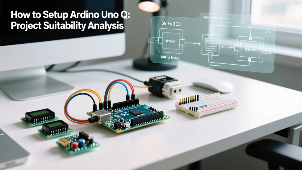
- Acquire a Qwiic Shield: Purchase a SparkFun Qwiic Shield for Arduino (DEV-14477 or equivalent). This shield routes the Uno's I2C pins through a PCA9306 or BSS138 logic level translator and includes an AP2112K-3.3 voltage regulator to step down the Uno's 5V to a safe 3.3V for the sensor network.
- Mount the Shield: Align the 1x6 and 1x8 female headers with the Uno's male pins. Ensure no pins are bent.
- Daisy-Chain the Sensors: Use standard 100mm to 500mm 4-pin JST-SH Qwiic cables to connect your breakout boards. The physical order of the chain does not matter for I2C, as addressing is handled in software.
- Power Budgeting: The Uno's onboard 5V regulator (or USB VBUS) can safely supply about 500mA. Ensure your entire Qwiic chain (including OLED displays and IMUs) does not exceed 300mA at 3.3V to prevent thermal throttling of the shield's voltage regulator.
Software Configuration in Arduino IDE 2.3
With the hardware safely translated, you must configure the I2C bus in software. The SparkFun Qwiic ecosystem provides unified Arduino libraries for nearly all their sensors, but verifying bus communication is always the first step.
Open Arduino IDE 2.3 (or newer) and upload an I2C Scanner sketch to map the hexadecimal addresses of your connected Qwiic devices.
#include <Wire.h>

void setup() {
  Wire.begin();
  Serial.begin(115200);
  while (!Serial); // Wait for serial monitor
  Serial.println('\nI2C Scanner - Qwiic Bus Check');
}

void loop() {
  byte error, address;
  int nDevices = 0;
  Serial.println('Scanning...');

  for(address = 1; address < 127; address++ ) {
    Wire.beginTransmission(address);
    error = Wire.endTransmission();
    if (error == 0) {
      Serial.print('I2C device found at address 0x');
      if (address < 16) Serial.print('0');
      Serial.println(address, HEX);
      nDevices++;
    }
  }
  if (nDevices == 0) Serial.println('No I2C devices found\n');
  delay(5000); // Scan every 5 seconds
}
Edge Cases & I2C Bus Failure Modes
Real-world engineering requires anticipating failure modes. When setting up a complex Qwiic network on an Arduino Uno, you will inevitably encounter the following edge cases:
- Pull-Up Resistor Conflicts: Every Qwiic breakout board includes 4.7kΩ I2C pull-up resistors tied to 3.3V. If you daisy-chain five sensors, you place five 4.7kΩ resistors in parallel, resulting in an equivalent resistance of ~940Ω. This pulls excessive current through the open-drain I2C pins, violating the NXP I2C-bus specification (max 3mA sink current). The logic LOW voltage will rise above the 0.8V threshold, causing bus lockups. Solution: Cut the I2C PU jumper on all but one breakout board in the chain.
- Bus Capacitance Limits: The I2C protocol is limited by the parasitic capacitance of the wires and pins. The maximum allowed bus capacitance is 400pF. Using long Qwiic cables (over 500mm) or chaining more than 8-10 devices will increase capacitance, rounding off the square wave signals and causing data corruption. Solution: Keep total cable length under 1 meter and use 400kHz Fast Mode via
Wire.setClock(400000);. - Address Collisions: Many identical Qwiic sensors (e.g., multiple TMP102 temperature sensors) share the same default I2C address. Solution: Use the ADR jumper pads on the breakouts to shift the address, or utilize an I2C Multiplexer (like the TCA9548A) to isolate the devices onto separate sub-buses.
Final Verdict for 2026 Prototyping
Learning how to setup arduino uno q (Qwiic) is an essential skill for rapid hardware prototyping. The suitability of this setup is overwhelmingly positive for environmental monitoring, robotics sensor fusion, and educational environments where wiring complexity is a barrier to entry. However, for production-grade deployments or high-speed data acquisition, engineers should pivot to SPI-based architectures or upgrade to microcontrollers with native CAN-bus support to bypass the physical limitations of the I2C protocol.