
The Hardware Reality: Choosing Your ESP32 Dev Board
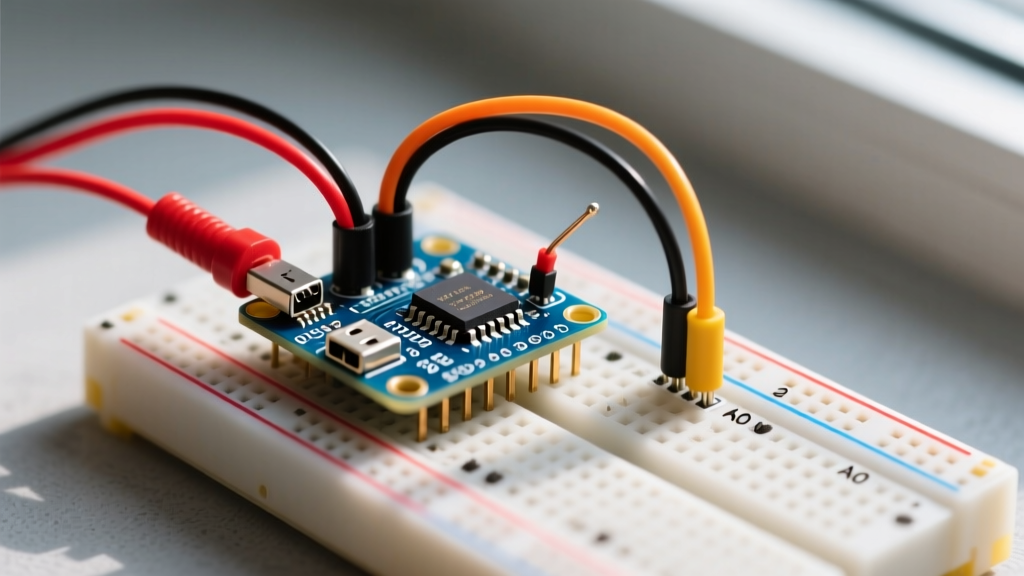
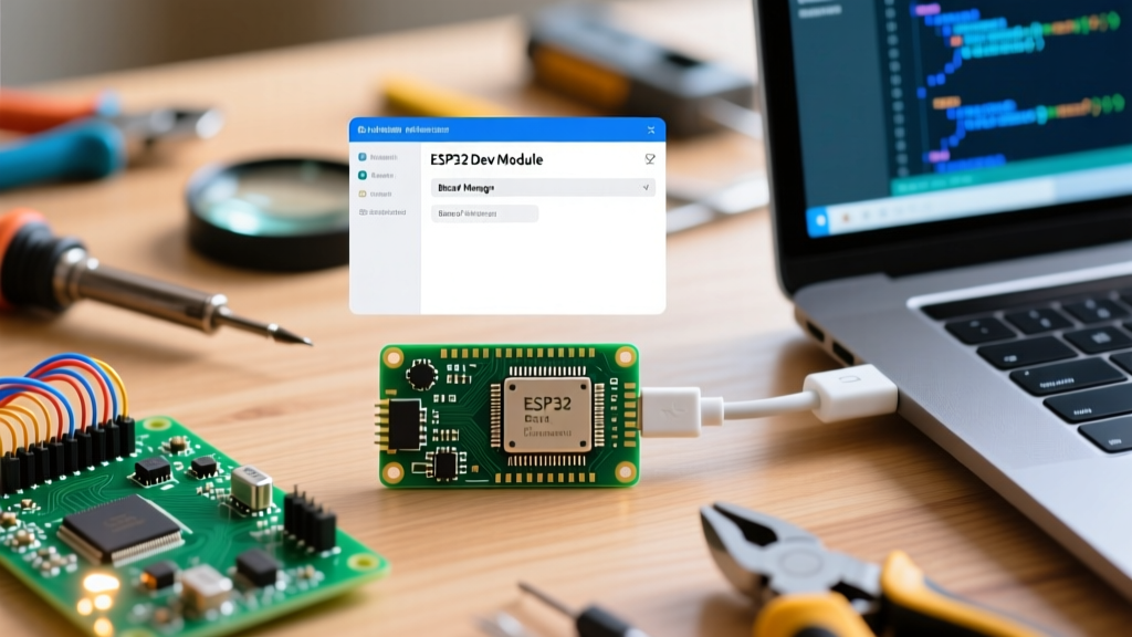
If you are wondering how to connect ESP32 to Arduino IDE, the first step actually happens before you even open the software. You need the right hardware and, more importantly, the right cable. In 2026, the market is flooded with ESP32 clones, but the underlying architecture remains dominated by two primary development boards: the classic ESP32-DevKitC V4 (featuring the ESP32-WROOM-32E module) and the newer, AI-capable ESP32-S3-DevKitC-1.
For your first project, the standard ESP32-WROOM-32E DevKitC is the undisputed champion. It costs between $4.50 and $6.00, features dual-core 240MHz processing, and has massive community support. However, the most common failure point for beginners isn't the code—it is the USB cable.
Expert Warning: Over 70% of 'dead on arrival' ESP32 boards are actually just victims of charge-only USB cables. A charge-only cable lacks the internal D+ and D- data wires (usually 28AWG). If your computer doesn't play the USB connection chime when you plug the board in, throw the cable away and use a verified data-sync cable.
Identifying Your Serial Bridge Chip
Look closely at the small black chip located right next to the USB port on your dev board. This is the USB-to-UART bridge. It will be one of two models:
- CP2102 (Silicon Labs): Usually found on higher-quality boards. Excellent native support on macOS and Linux, but requires a specific driver for Windows 11.
- CH340 (WCH): Found on budget clones. Requires a third-party driver on almost all operating systems.
Step 1: Installing the USB-to-UART Bridge Drivers
Before the Arduino IDE can talk to your microcontroller, your operating system needs to understand the serial bridge. If you have a CP2102 chip, you must download the official Virtual COM Port (VCP) drivers. You can find the latest stable releases directly from the Silicon Labs VCP Driver page.
For Windows users, download the CP210x Universal Windows Driver. Extract the ZIP file, right-click the silabser.inf file, and select 'Install'. Once installed, plug in your ESP32. Open the Windows Device Manager and expand the 'Ports (COM & LPT)' section. You should see 'Silicon Labs CP210x USB to UART Bridge (COM3)' (your COM number will vary). Note this COM number; you will need it later.
Step 2: Adding the Espressif Board Manager URL
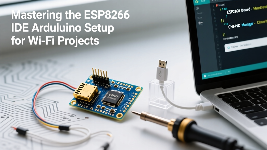
The standard Arduino IDE does not include ESP32 support out of the box because the ESP32 is manufactured by Espressif, not Arduino. You must add a custom Board Manager URL. This tells the IDE where to find the compiler toolchains and hardware definitions.
- Open Arduino IDE (version 2.3.x or newer is highly recommended for 2026 workflows).
- Navigate to File > Preferences (or Arduino IDE > Settings on macOS).
- Locate the 'Additional boards manager URLs' field at the bottom.
- Paste the official Espressif JSON link:
https://raw.githubusercontent.com/espressif/arduino-esp32/gh-pages/package_esp32_index.json - Click 'OK' to save.
This specific URL is maintained by Espressif and ensures you get the latest stable releases, including the crucial v3.0+ Arduino Core updates which overhauled the Wi-Fi and Bluetooth LE stacks.
Step 3: Installing and Configuring the ESP32 Core
Now, click on the Board Manager icon on the left-hand sidebar (it looks like a circuit board). Search for esp32. You will see a package titled 'esp32 by Espressif Systems'. Click Install. This will download approximately 300MB of toolchains, including the Xtensa GCC compiler and esptool.py.
Once installed, connect your ESP32 to your PC. Go to Tools > Board > esp32 and select DOIT ESP32 DEVKIT V1 (this is the most universally compatible profile for generic DevKitC boards). Next, go to Tools > Port and select the COM port you identified in Step 1.
Critical Board Settings Matrix
The default settings are often suboptimal for modern development. Adjust your Tools menu to match this matrix for the best upload stability and memory management:
| Parameter | Recommended Setting | Why This Matters |
|---|---|---|
| Upload Speed | 921600 | Flashes the 4MB memory in seconds rather than minutes. Drop to 115200 only if you get timeout errors. |
| CPU Frequency | 240MHz (WiFi/BT) | Maximum performance. Use 80MHz only if you are strictly optimizing for battery life on a deep-sleep project. |
| Flash Frequency | 80MHz | Matches the physical QSPI flash chip speed on the WROOM-32E module. |
| Partition Scheme | Default 4MB with spiffs | Gives you 1.2MB for code and 1.5MB for filesystem. Switch to 'Huge APP' if your code exceeds 1.2MB. |
| Erase All Flash | Disabled | Enable this ONLY if you are migrating from a different framework (like ESP-IDF or MicroPython) and need a clean slate. |
Step 4: The 'BOOT Button' Hardware Hack
When learning how to connect ESP32 to Arduino IDE, you will inevitably hit the 'Timed out waiting for packet header' error. This happens because cheap clone boards often lack the auto-reset circuitry (using DTR/RTS serial lines) required to automatically put the ESP32 into bootloader mode.
To bypass this hardware limitation, use the manual BOOT button trick:
- Click the 'Upload' button in the Arduino IDE.
- Watch the console output at the bottom. Wait until it says:
Connecting... - Immediately press and hold the BOOT button on the ESP32 board.
- After 2 seconds, release the BOOT button.
This manually pulls GPIO 0 low during the reset sequence, forcing the chip into UART bootloader mode. The upload will immediately resume and complete successfully.
Step 5: Your First Project - GPIO 2 Blink
Let us verify the entire toolchain with a simple hardware test. The ESP32-DevKitC V4 has a blue onboard LED connected to GPIO 2. We will write a script to blink it, proving that compilation, serial communication, and flash writing are all functioning.
The Code
// ESP32 GPIO 2 Blink Test
// Compatible with Espressif Arduino Core v3.x

#define LED_PIN 2

void setup() {
  Serial.begin(115200);
  pinMode(LED_PIN, OUTPUT);
  Serial.println("ESP32 GPIO 2 Blink Initialized.");
}

void loop() {
  digitalWrite(LED_PIN, HIGH);
  Serial.println("LED ON");
  delay(1000);

  digitalWrite(LED_PIN, LOW);
  Serial.println("LED OFF");
  delay(1000);
}
Copy this code into your IDE, click Upload, and open the Serial Monitor (set to 115200 baud). You should see the 'LED ON/OFF' text printing every second, and the blue light on the board will flash in sync. For deeper architectural details on GPIO mapping, consult the Espressif Arduino Core Documentation.
Troubleshooting Matrix: Common Upload Failures
Even with perfect settings, environmental factors can disrupt the connection. Use this matrix to diagnose issues quickly.
| Error Message | Root Cause | Expert Fix |
|---|---|---|
| Port greyed out / Not listed | Missing driver or charge-only cable. | Verify cable with a smartphone data transfer test. Reinstall CP210x/CH340 drivers. |
| Failed to connect: Timed out | Auto-reset circuit failure. | Use the BOOT button trick detailed in Step 4. Check if GPIO 0 is pulled high by external circuitry. |
| esptool.py: error: Invalid head of packet | Baud rate mismatch or USB hub voltage drop. | Plug directly into the motherboard's rear USB ports. Lower Upload Speed to 460800 or 115200. |
| Sketch too big / Partition error | Code exceeds allocated APP partition. | Change Partition Scheme to 'Huge APP (3MB No OTA/1MB SPIFFS)' in the Tools menu. |
Final Thoughts on Platform Selection
Understanding how to connect ESP32 to Arduino IDE is just the gateway. The Arduino IDE abstracts away the complexities of the underlying FreeRTOS operating system, making it perfect for rapid prototyping. However, as your projects scale into multi-threaded industrial IoT applications in 2026, you may eventually need to transition to the native ESP-IDF framework. For now, master the Arduino core, leverage the massive library ecosystem, and start building your Wi-Fi connected sensors.
For more information on managing different microcontroller cores within the IDE, review the official Arduino Cores Guide to understand how toolchains are managed in the background.