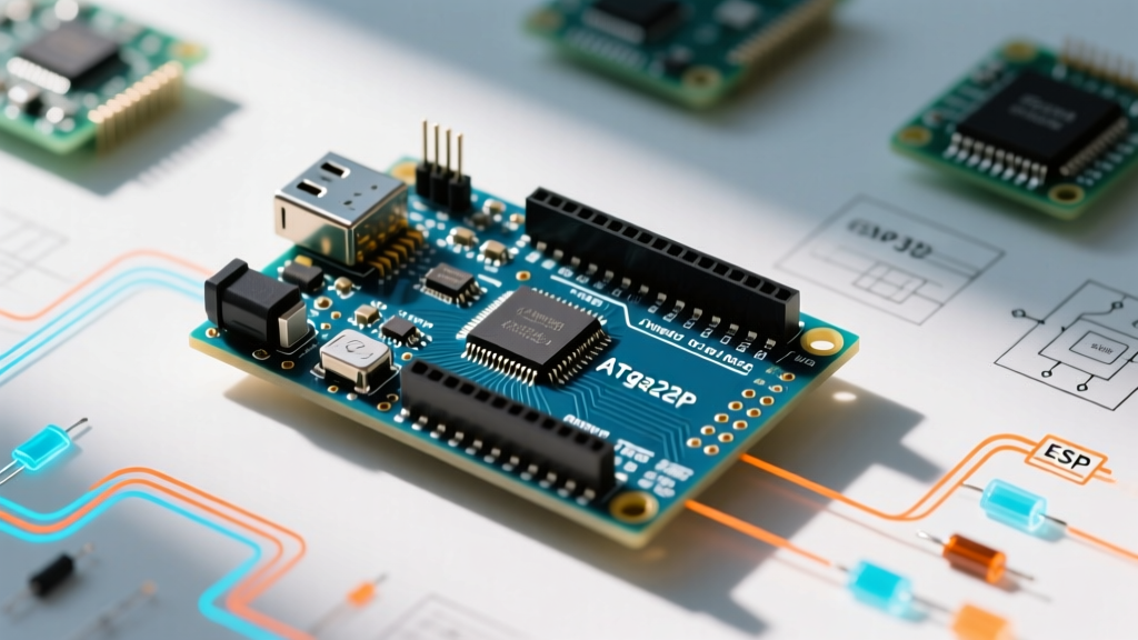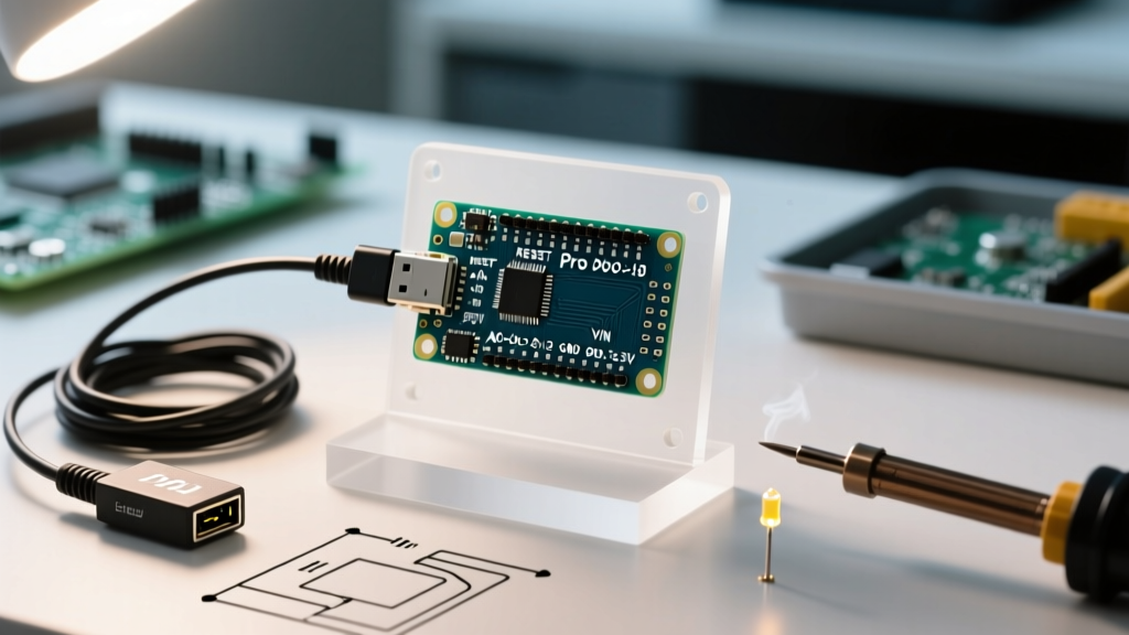

The Arduino Micro is a staple in the DIY electronics community, particularly for Human Interface Device (HID) projects like custom macro keyboards, flight simulators, and mouse emulators. Its secret weapon is the ATmega32U4 microcontroller, which features native USB communication capabilities, eliminating the need for a secondary USB-to-Serial converter chip. However, this architectural choice creates a significant hurdle for developers: the Arduino Micro pin layout diverges sharply from the ubiquitous ATmega328P-based Arduino Uno. When you attempt to use community-written libraries or copy-paste sketches designed for the Uno, the Micro's unique pin mapping often results in silent failures, broken SPI/I2C communications, and frustrating debugging sessions.
The ATmega32U4 Dilemma: Why the Arduino Micro Pin Layout Breaks Libraries
To understand why third-party libraries fail on the Micro, you must look at the underlying C++ hardware abstraction layer. In the official ArduinoCore-avr pins_arduino.h repository, the mapping for the ATmega32U4 is fundamentally different from the ATmega328P. Many older or poorly maintained community libraries hardcode pin definitions (e.g., assuming D11 is MOSI or A4 is SDA) rather than using the portable SPI.h or Wire.h macros. As of 2026, while modern IDE 2.x environments have improved static analysis, thousands of legacy libraries on GitHub still contain hardcoded and Nano bias, leaving Micro users to manually patch code.
Hardware Mapping Matrix: Uno vs. Micro
Before attempting to patch a library, you need a clear reference of where the physical traces actually route on the PCB. Below is a critical comparison matrix highlighting the most common failure points when migrating from an Uno to a Micro.
| Function | Arduino Uno (ATmega328P) | Arduino Micro (ATmega32U4) | Common Library Failure Mode |
|---|---|---|---|
| SPI (MOSI) | D11 | ICSP Header / D16 (Internal) | RF24 and display libraries fail if hardcoded to D11. |
| SPI (MISO) | D12 | ICSP Header / D14 (Internal) | SD card modules fail to initialize. |
| SPI (SCK) | D13 | ICSP Header / D15 (Internal) | Clock signal never reaches the sensor. |
| I2C (SDA) | A4 | D2 | LCD2004 I2C backpacks show blank screens. |
| I2C (SCL) | A5 | D3 | IMU sensors (MPU6050) fail wire handshake. |
| Hardware UART | D0 (RX), D1 (TX) | D0 (RX1), D1 (TX1) / Serial1 | GPS modules fail; USB Serial intercepts data. |
Community Workarounds for Hardcoded Libraries
When dealing with the Arduino Micro pin layout, the community has developed several standard operating procedures to bypass hardcoded limitations without rewriting entire libraries from scratch.
1. The SPI and ICSP Header Bypass
If you are wiring an nRF24L01 radio module or an ST7735 TFT display, you cannot use the standard digital header pins for SPI on the Micro. The physical pins labeled 11, 12, and 13 on the Micro's silkscreen do not route to the SPI peripheral. Instead, you must wire your module's MOSI, MISO, and SCK directly to the 2x3 ICSP header located near the center of the board. Leave the Chip Select (CS/SS) pin on D10 (which is consistent across both boards). In your sketch, initialize the library using the hardware SPI object rather than software SPI pins.
2. The Serial vs. Serial1 Trap
This is the most frequent support ticket in microcontroller forums. On the Uno, Serial.print() sends data to the hardware UART pins (D0/D1). On the Micro, Serial refers exclusively to the virtual USB CDC connection to your PC. If you connect a hardware GPS module or a Bluetooth HC-05 to D0 and D1, you must use Serial1.begin(9600) and Serial1.read() in your code. Libraries that hardcode Serial for external comms will silently fail on the Micro.
Expert Tip: When debugging Serial1 issues on the Micro, use the native USBSerialto create a software bridge. Write a simple loop that reads fromSerial1and prints toSerial, allowing you to view hardware UART traffic in the standard IDE 2.x serial monitor without needing a secondary USB-to-TTL adapter.
3. I2C Pin Reassignment via Wire.h
Because the Arduino Micro routes I2C to D2 (SDA) and D3 (SCL), shields designed for the Uno's A4/A5 I2C routing will not make physical contact with the correct pins. If you are using a breakout board, wire directly to D2 and D3. If you are forced to use a shield, the community workaround is to abandon the hardware Wire library and use a software I2C library like SoftwareWire, defining A4 and A5 as software I2C pins to maintain physical shield compatibility at the cost of slightly higher CPU overhead.
Step-by-Step: Patching a Non-Compliant Library
When a library refuses to compile or function due to the Micro's pin layout, you can patch it locally. Here is the professional workflow for modifying a third-party library to support the ATmega32U4.
- Locate the Hardcoded Pins: Open the library's
.cppand.hfiles in a text editor. Search for integers like11,12,13,A4, orA it is highly recommended to consult community-maintained pinout diagrams, such as the legendary PJRC ATmega32U4 reference charts, which map the Arduino digital aliases to the actual AVR port registers (e.g., PORTB, PORTD, PORTF) for advanced bitwise manipulation.Frequently Asked Questions
Can I use the analog pins A6 through A11 as digital I/O on the Micro?
No. Unlike the Arduino Mega, the A6 through A11 pins on the Arduino Micro are strictly connected to the ADC (Analog-to-Digital Converter) multiplexer. They lack the internal digital pull-up resistors and output drivers required for
digitalWrite()ordigitalRead(). Attempting to use them for digital buttons or LEDs will result in floating states and erratic behavior.Why does my NeoPixel strip flicker on the Arduino Micro?
The Adafruit NeoPixel library is fully compatible with the Arduino Micro pin layout, but the ATmega32U4's native USB interrupts can occasionally disrupt the strict timing required for WS2812B LEDs. If you experience flickering, wrap your
strip.show()function in anoInterrupts()andinterrupts()block to ensure the USB polling cycle doesn't stutter the data line.