
The Definitive Beginner's Guide to Powering the Arduino Nano
Choosing the correct power supply for Arduino Nano projects is one of the most common stumbling blocks for beginners. While the Nano is a remarkably resilient microcontroller board based on the ATmega328P, feeding it the wrong voltage, excessive current, or noisy power can lead to erratic behavior, random resets, or permanent silicon damage. Whether you are building a portable weather station or a stationary robotics controller, understanding the Nano's internal power architecture is critical.
In this guide, we will dissect the three ways to power the board, explain the thermal limits of the onboard voltage regulator, and provide actionable wiring diagrams for real-world 2026 project builds.
Understanding the Nano's Internal Power Architecture
Before connecting any battery or wall adapter, you must understand how power routes through the Nano. According to the official Arduino Nano documentation, the board operates at 5V logic levels, but it accepts a range of input voltages depending on the pin you use. The board features three primary power domains:
- The USB Interface: Modern Nanos (and most third-party clones) use the WCH CH340G or CH341A USB-to-serial chip. This chip requires a clean 5V supply from your computer's USB port, which is protected by a 500mA resettable polyfuse.
- The Onboard Linear Regulator: This SMD component (typically an LM1117-5.0 or similar LDO) steps down higher voltages from the VIN pin to a stable 5V.
- The 5V Rail: This is the direct 5V bus that powers the ATmega328P microcontroller and your external sensors.
The Three Ways to Power Your Nano
1. USB Mini-B (The Safest Method)
Plugging a standard 5V USB power bank or wall charger into the Mini-B port is the safest way to power your Nano. The USB line has built-in overcurrent protection. However, be aware that the Mini-B connector on cheap clone boards often has weak solder joints. If your project requires frequent plugging and unplugging, secure the cable with a zip-tie to prevent pad lift-off.
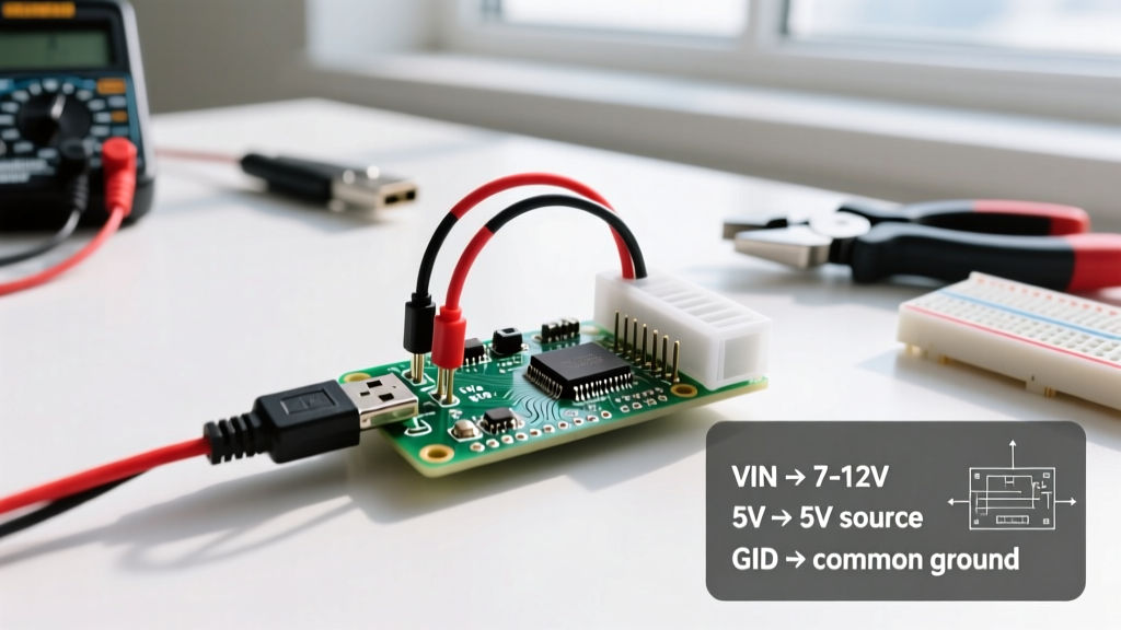
2. The VIN Pin (7V to 12V Recommended)
The VIN (Voltage In) pin routes directly to the input of the onboard linear regulator. While the LM1117 datasheet states an absolute maximum input of 15V, pushing 15V into a Nano with no heatsink is a recipe for thermal shutdown. The recommended sweet spot for VIN is 7V to 9V.
3. The 5V Pin (Direct Injection - Proceed with Caution)
You can inject exactly 5V directly into the '5V' pin. This bypasses the onboard regulator entirely, meaning zero heat is generated on the board. Warning: If you accidentally supply 5.5V or higher to this pin, you will instantly destroy the ATmega328P and the USB interface chip. There is no protection diode on this line.
Expert Warning: The Backfeed Hazard
Many budget Nano clones omit the Schottky protection diode between the USB 5V line and the regulator output. If you power the Nano via the VIN pin at 9V while simultaneously connected to your PC via USB, the 9V can backfeed into your computer's USB port, potentially frying your motherboard. Always unplug the USB cable when testing high-voltage VIN setups.
The Thermal Bottleneck: Why Your Nano Gets Hot
The most misunderstood aspect of designing a power supply for Arduino Nano projects is heat dissipation. The onboard linear regulator operates by burning off excess voltage as heat. We calculate this using the power dissipation formula:
P(dissipated) = (V_in - V_out) x I_load
Let's look at a real-world scenario. Suppose you power your Nano with a 12V wall adapter via the VIN pin, and your attached sensors and relays draw 150mA (0.15A) from the 5V rail.
- Voltage Drop: 12V - 5V = 7V
- Power Dissipated: 7V x 0.15A = 1.05 Watts
A standard SOT-223 package regulator without a dedicated copper pour heatsink has a thermal resistance of roughly 50°C/W. This means the regulator's internal junction temperature will rise by 52.5°C above ambient room temperature. If your room is 25°C, the regulator is sitting at 77.5°C. At this temperature, the regulator's internal thermal protection will begin to throttle the voltage, causing your Nano to brownout and reset. As detailed in SparkFun's guide to voltage regulators, linear regulators are highly inefficient for high-current or high-voltage-differential applications.
Power Source Comparison Matrix
To help you select the right power supply for your specific build, refer to the comparison table below.
| Power Source | Input Pin | Est. Cost (2026) | Max Safe Current | Best Use Case |
|---|---|---|---|---|
| 5V USB Power Bank (10,000mAh) | USB Mini-B | $15 - $25 | 500mA (Polyfuse limit) | Portable data loggers, wearables |
| 9V PP3 Alkaline Battery | VIN | $3 - $5 | 50mA (Voltage sags heavily) | Avoid. High internal resistance causes brownouts. |
| 12V DC Wall Adapter (1A) | VIN | $8 - $12 | 100mA (Thermal limit) | Stationary projects with few sensors |
| 2S Li-Po Battery (7.4V) + Buck | 5V Pin | $18 - $30 | 2A+ (Depends on Buck) | Robotics, motorized projects, high current |
Step-by-Step: Wiring a High-Efficiency Buck Converter
If your project requires driving relays, servos, or LED strips alongside the Nano, you must abandon the onboard linear regulator. Instead, use a switching buck converter like the popular LM2596 module (widely available for under $4). Switching converters step down voltage with 85-90% efficiency, generating almost no heat.
Step 1: Prepare the LM2596 Module
- Connect a 9V or 12V battery pack to the IN+ and IN- terminals of the LM2596 module.
- Using a digital multimeter, probe the OUT+ and OUT- terminals.
- Use a small flathead screwdriver to turn the blue trim-potentiometer on the module until your multimeter reads exactly 5.00V.
Step 2: Connect to the Arduino Nano
- Disconnect the battery.
- Connect the LM2596 OUT+ to the Nano's 5V pin (NOT the VIN pin).
- Connect the LM2596 OUT- to the Nano's GND pin.
- Use 22 AWG stranded silicone wire for these connections to handle up to 3A safely without voltage drop.
Step 3: Add Decoupling Capacitors
Switching converters introduce high-frequency ripple noise that can cause inaccurate readings on the Nano's analog-to-digital converter (ADC) pins. To fix this, solder a 100µF electrolytic capacitor and a 100nF ceramic capacitor in parallel across the 5V and GND pins directly on the Nano header. This creates a low-impedance path for noise, ensuring pristine analog readings.
Common Beginner Mistakes and Troubleshooting
The '9V Battery' Myth
Many beginner kits include a 9V PP3 battery snap connector. While 9V is technically within the VIN limits, PP3 batteries have a very high internal resistance (often 1 to 2 Ohms). When the Nano's USB interface chip and ATmega draw a sudden spike of 100mA during Wi-Fi transmission (if using an attached ESP module) or servo movement, the battery voltage sags below the regulator's dropout voltage. The Nano will continuously reset. Always use 6x AA battery packs (9V nominal, low resistance) or 18650 Li-Ion cells instead.
ADC Noise and Floating Grounds
If your analog sensors are returning jittery values, your power supply is likely the culprit. Ensure that the ground of your external power supply is tied directly to the Nano's GND pin. Never rely on breadboard ground rails for high-current loads like motors; the spring contacts in cheap breadboards have high resistance, which creates a 'floating ground' differential that the Nano reads as sensor noise.
The Flickering 'L' LED
If the onboard 'L' LED (pin 13) is flickering dimly or pulsing, your Nano is experiencing a brownout. The ATmega328P's internal brownout detection (BOD) is typically set to 2.7V or 4.3V. If your 5V rail dips due to a weak power supply or long, thin wires, the BOD triggers a reset. Shorten your power wires and upgrade to a higher-amperage power supply to resolve this immediately.
Final Thoughts on Power Management
Selecting the right power supply for Arduino Nano projects comes down to understanding your current draw and thermal limits. For simple, low-power sensor nodes, a 5V USB power bank via the Mini-B port is unbeatable for safety and ease of use. For robotics and high-current applications, bypassing the internal regulator with an external LM2596 buck converter feeding the 5V pin is the professional standard. By respecting the limits of the silicon and using proper decoupling techniques, your Nano projects will run reliably for years to come.