
The Reality of the Arduino Uno Pin Layout
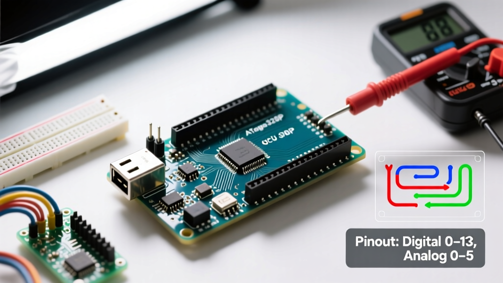
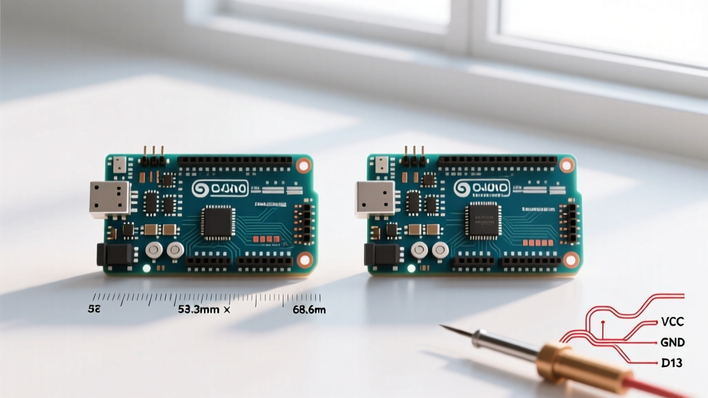
When engineers and makers evaluate a microcontroller for a new build, the physical footprint often dictates the choice. The 'Arduino Uno pin' layout has become the de facto industry standard for development boards, replicated by hundreds of third-party manufacturers. However, treating all 20 I/O headers as equal resources is a critical mistake that leads to field failures, noisy sensor data, and thermal shutdowns. As of 2026, with the market split between the classic ATmega328P-based Uno R3 (retailing around $27.50 for genuine boards) and the modern RA4M1-based Uno R4 Minima (priced at $19.99), understanding the exact electrical suitability of each pin is more important than ever.
This project suitability analysis breaks down the exact current limits, peripheral overlaps, and thermal constraints of the standard Uno pinout. By mapping specific project archetypes to the board's actual hardware capabilities, you can determine whether the Uno is the right foundation or if you need to pivot to an ESP32 or Arduino Mega.
Digital I/O Pins (D0–D13): Logic and PWM Constraints
The Uno features 14 digital I/O pins, but their suitability varies wildly depending on internal peripheral routing. According to the Arduino Official Hardware Documentation, each pin can safely source or sink 20mA, with an absolute maximum rating of 40mA. Pushing a pin to 40mA continuously degrades the silicon over time and causes voltage droop.
The UART Conflict (D0 and D1)
Pins D0 (RX) and D1 (TX) are hardwired to the onboard USB-to-Serial converter (the ATmega16U2 on the R3). Suitability Verdict: Never use D0 and D1 for general-purpose digital I/O or PWM in projects that require Serial debugging or USB data logging. Connecting external loads to these pins can interfere with the bootloader sequence, causing the board to hang during firmware uploads.
PWM and Timer Overlaps (D3, D5, D6, D9, D10, D11)
Six pins offer hardware Pulse Width Modulation (PWM), essential for motor speed control and LED dimming. However, these pins share internal hardware timers. For instance, D9 and D10 share Timer1, while D5 and D6 share Timer0. If your project uses the tone() library to drive a piezo buzzer on D3, it will conflict with PWM outputs on D9 and D10 because they share Timer2 resources. Suitability Verdict: Ideal for simple DC motor control via H-bridges (like the L298N), but unsuitable for complex multi-axis CNC routing where independent, high-frequency timer interrupts are required.
Analog Inputs (A0–A5): ADC Resolution and Noise
The analog pins double as digital I/O, but their primary role is reading sensors via the Analog-to-Digital Converter (ADC). The classic Uno R3 utilizes a 10-bit ADC, yielding 1,024 discrete steps. With a default 5V reference, each step represents approximately 4.88mV.
The I2C Bottleneck (A4 and A5)
Pins A4 (SDA) and A5 (SCL) are routed to the hardware TWI (Two-Wire Interface) bus. While you can use them as standard analog inputs, doing so disables your ability to use I2C sensors (like the BME280 or MPU6050) or I2C OLED displays. Suitability Verdict: If your project requires an I2C display alongside multiple analog sensors, the Uno's 6 analog pins are effectively reduced to 4. For environmental monitoring stations requiring 5+ analog sensors, the Uno is unsuitable; consider the Arduino Nano Every or a Teensy 4.0 instead.
Pro-Tip for ADC Stability: When reading high-impedance sensors (like a resistive soil moisture probe) on A0-A3, the internal sample-and-hold capacitor may not charge fully, leading to jittery readings. Place a 100nF ceramic decoupling capacitor between the analog input pin and GND to stabilize the voltage during the ADC sampling window.
Power Pin Limitations and Thermal Failure Modes
The most misunderstood aspect of the Arduino Uno pin layout is the power header. Misallocating power draws is the number one cause of catastrophic board failure in DIY projects.
The 5V Pin vs. Vin: A Thermal Trap
The 5V pin bypasses the onboard voltage regulator and connects directly to the 5V rail. If you power the Uno via USB, this pin can safely supply up to 500mA (limited by the USB polyfuse). However, if you power the board via the barrel jack or the Vin pin, the current must pass through the onboard linear regulator (typically an NCP1117ST50T3G).
Linear regulators dissipate excess voltage as heat. The power dissipation formula is P = (Vin - 5V) * I. If you connect a 12V power supply to Vin and draw 300mA from the 5V pin to power a string of WS2812B LEDs, the regulator must dissipate (12V - 5V) * 0.3A = 2.1 Watts. The SOT-223 package has a thermal resistance of roughly 50°C/W. This results in a 105°C temperature rise above ambient, instantly triggering the regulator's internal thermal shutdown. Suitability Verdict: The Uno's 5V pin is entirely unsuitable for powering high-current loads (like NeoPixels or high-torque servos) when fed via the barrel jack. Always use an external buck converter (like the LM2596) for loads exceeding 100mA.
Project Suitability Matrix: Does the Uno Fit?
To streamline your component selection, we have mapped common 2026 maker projects against the physical and logical limits of the Arduino Uno pinout.
| Project Archetype | Pin Demand | Uno Suitability | Primary Bottleneck | Recommended Alternative |
|---|---|---|---|---|
| Smart Home Relay Hub (8-Channel) | 8x Digital Out, I2C | High (5/5) | None. Fits perfectly within D2-D12 limits. | Arduino Nano (for compact PCB integration) |
| GPS Data Logger with SD Card | UART, SPI, 1x Analog | Medium (3/5) | D0/D1 UART conflict with USB debugging. | ESP32 (Hardware Serial2 + native SDIO) |
| RGB LED Matrix Display (WS2812B) | 1x PWM, 5V Power | Low (2/5) | 5V pin current limit; RAM limits for large arrays. | Raspberry Pi Pico (PIO state machines + high current) |
| Multi-Sensor Weather Station | I2C, SPI, 4x Analog | Medium (3/5) | A4/A5 I2C overlap reduces available analog pins. | Arduino Nano Every (More ADC channels & I2C buses) |
| Self-Balancing Robot (PID Control) | I2C, 2x PWM, Interrupts | High (4/5) | D2/D3 interrupt limits if encoders are added. | Teensy 4.1 (FPU for fast PID math + abundant pins) |
Edge Cases: When Uno Pins Fail in the Field
Even when a project fits the Uno pinout on paper, real-world physics can cause unexpected failures. Here are the most common edge cases documented in the Microchip ATmega328P Datasheet and field engineering reports.
1. Inductive Kickback on Relay Pins
Connecting a 5V relay coil directly to a digital I/O pin (even through a standard 2N2222 transistor) without a flyback diode will generate a massive back-EMF spike when the coil de-energizes. This spike can exceed the 40V absolute maximum rating of the ATmega328P's I/O protection diodes, permanently latching the pin in a HIGH state or destroying the microcontroller's internal port register. Always use a 1N4148 diode reverse-biased across the relay coil.
2. Capacitive Loading on I2C (A4/A5)
When routing I2C wires longer than 30cm to remote sensors, the parasitic capacitance of the cable increases. The Uno's internal pull-up resistors (typically 20kΩ to 50kΩ) are too weak to pull the line HIGH fast enough, resulting in corrupted data packets and 'NaN' sensor readings. The fix is to disable internal pull-ups and install external 4.7kΩ pull-up resistors directly on the sensor breakout board, or use an I2C bus extender like the PCA9615.
3. Voltage Divider Inaccuracies
Using a simple resistor voltage divider to step down a 12V battery signal to the 5V analog pin (A0) is a common practice. However, as detailed in SparkFun's Voltage Divider Tutorial, the ADC's internal sampling impedance (roughly 10kΩ to 100kΩ) forms a parallel circuit with your divider, skewing the readings. To maintain accuracy, ensure the Thevenin equivalent resistance of your voltage divider is strictly below 10kΩ, or buffer it with an op-amp like the LM358.
Final Verdict for Makers and Engineers
The Arduino Uno pin layout remains a masterpiece of accessible hardware design, but it is not a universal solution. Its 20mA per-pin limit, shared hardware timers, and thermally constrained 5V regulator make it highly suitable for low-power logic control, basic educational robotics, and simple relay switching. It is fundamentally unsuitable for high-current LED matrices, multi-axis motor control, or projects requiring extensive analog sensing alongside I2C communication. By respecting the electrical boundaries of each specific pin, you can ensure your 2026 builds are robust, reliable, and ready for deployment.