
The 2026 Landscape: Where Do Arduino Uno R3 Pins Fit?
In an era dominated by 3.3V logic, dual-core ESP32s, and the Raspberry Pi Pico's PIO state machines, the classic Arduino Uno R3 might seem like a relic. Yet, it remains a staple on workbenches worldwide. Why? Because the Arduino Uno R3 pins offer a forgiving, 5V-tolerant, and heavily documented interface that is unmatched for specific legacy integrations, educational setups, and straightforward 5V sensor arrays.
However, treating the Uno R3 as a universal solution leads to frustrating hardware bottlenecks. To determine if the Uno R3 is the right microcontroller for your next build, we must move beyond basic pinout diagrams and perform a rigorous project suitability analysis based on the actual silicon limitations of the ATmega328P.
The Silicon Reality: ATmega328P Pin Constraints
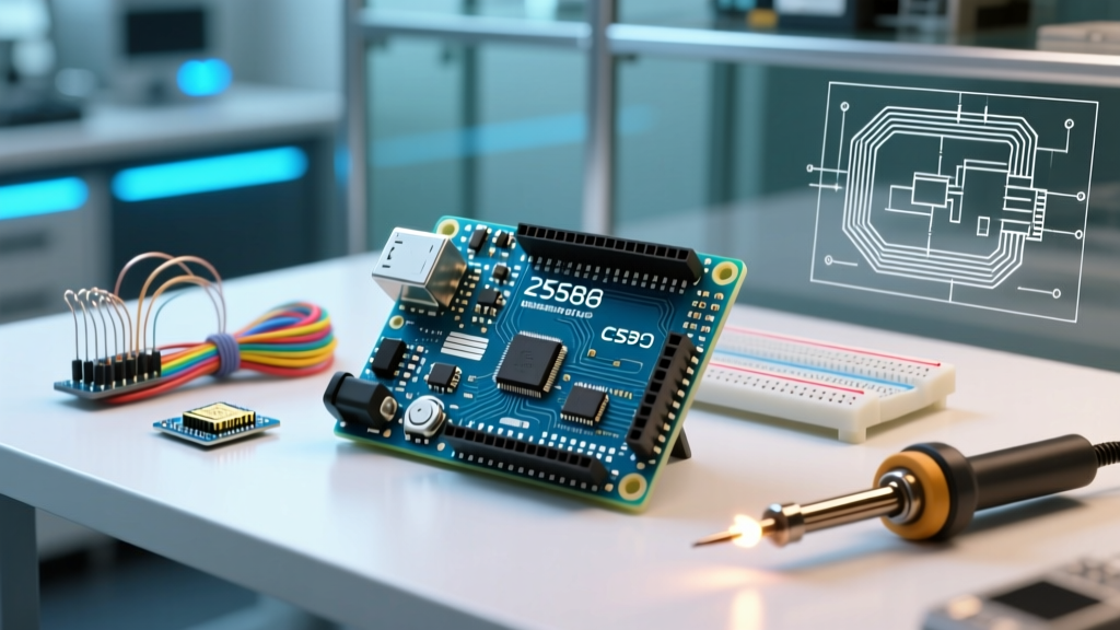
The Uno R3 is essentially a breakout board for the Microchip ATmega328P microcontroller. While it exposes 20 accessible I/O pins on the female headers, not all pins are created equal. Understanding the hidden multiplexing and hardware timer conflicts is critical for project success.
Digital I/O and Hidden Conflicts
The board features 14 digital I/O pins (D0-D13). However, your usable pin count shrinks rapidly depending on your communication protocols:
- Serial (UART): Pins 0 (RX) and 1 (TX) are hardwired to the ATmega16U2 USB-to-Serial chip. Using these for standard digital I/O will cause conflicts with the Serial Monitor and can lead to boot failures if pin 0 is pulled low during reset.
- SPI Bus: Pins 10 (SS), 11 (MOSI), 12 (MISO), and 13 (SCK) are dedicated to the hardware SPI bus. If you are driving an SD card module, a TFT display, or an SPI DAC, these four pins are permanently consumed.
- Onboard LED: Pin 13 is tied to the onboard LED and its op-amp buffer. While usable as an input, its threshold voltages are altered by the buffer circuit, making it unsuitable for sensitive digital inputs.
The PWM and Timer Trap
Six pins support hardware Pulse Width Modulation (PWM): 3, 5, 6, 9, 10, and 11. A common failure mode for intermediate makers involves attempting to change the PWM frequency on Pins 5 and 6. These pins are controlled by Timer0, which is also responsible for core Arduino timing functions like millis(), micros(), and delay(). Altering Timer0's prescaler to achieve a higher PWM frequency for motor control will instantly break all time-dependent logic in your sketch.
Analog Inputs: Resolution and Reference Limits
The Uno R3 provides 6 analog input pins (A0-A5). These are routed to the ATmega328P's internal 10-bit Successive Approximation Register (SAR) ADC.
- Resolution: 10-bit yields 1,024 discrete steps. With the default 5V reference, each step represents approximately 4.88mV. This is sufficient for reading basic potentiometers or NTC thermistors, but entirely inadequate for precision load cells or low-voltage biomedical sensors (where a 24-bit external ADC like the HX711 is mandatory).
- Sample Rate: The default ADC clock prescaler is 128, resulting in a maximum sample rate of roughly 9.6 kHz. Attempting to sample audio signals directly through the analog pins will result in severe aliasing and Nyquist violations.
- The AREF Pin: For projects requiring higher precision in the 0-1.1V range, the Uno R3 exposes the AREF pin. By switching to the internal 1.1V bandgap reference via
analogReference(INTERNAL), you can achieve a much finer resolution of ~1.07mV per step, ideal for precise current-sensing shunt resistors.
Critical 2026 Note on A6 and A7: While some clone boards or SMD-based ATmega328P chips feature A6 and A7, the standard through-hole DIP-28 package used on the genuine Uno R3 does not have these pins physically connected. Do not design shields assuming A6/A7 availability on a standard Uno R3.
Project Suitability Matrix
Based on the electrical characteristics and pin multiplexing of the Arduino Uno R3, here is a suitability analysis for common DIY project categories in 2026.
| Project Category | Pin Suitability | Primary Bottleneck | Recommended Workaround |
|---|---|---|---|
| 5V Industrial Relay Control | High | Current sourcing limits (20mA/pin) | Use ULN2803 Darlington arrays or optocouplers; never drive relays directly from I/O pins. |
| Basic I2C Sensor Arrays | High | Bus capacitance limit (400pF) | Keep I2C traces short; use 4.7kΩ pull-ups to 5V on A4/A5. |
| Fast Motor Control (FOC) | Low | Lack of hardware quadrature encoders & low PWM frequency | Upgrade to an ESP32 or use a dedicated motor shield with its own logic. |
| Audio DSP / Synthesizers | Very Low | 2KB SRAM limit & 9.6kHz ADC sample rate | Use a Teensy 4.1 or Raspberry Pi Pico for audio processing. |
| LED Matrix / NeoPixel Arrays | Medium | SRAM exhaustion (1 byte per NeoPixel) | Limit to <500 LEDs; offload complex rendering to a dedicated LED driver. |
Power Delivery and Edge Case Failure Modes
When evaluating the Arduino Uno R3 Official Documentation, the power pins are often misunderstood, leading to catastrophic board failures in complex projects.
The 3.3V Regulator Misconception
The Uno R3 features a 3.3V output pin. Many makers assume this can power modern 3.3V peripherals like the ESP8266 or SD card adapters. This is a critical error. The 3.3V pin is sourced from the onboard LP2985 LDO regulator, which has a strict maximum current limit of 50mA. Attempting to draw 150mA for a Wi-Fi module will cause the regulator to overheat, drop out, and potentially destroy the ATmega16U2 USB interface chip.
I2C Bus Lockups and Capacitance
Pins A4 (SDA) and A5 (SCL) act as the I2C bus. According to the NXP I2C-bus Specification, the maximum allowable bus capacitance is 400pF. When daisy-chaining multiple 5V I2C sensors (like the BME280, MPU6050, and an OLED display), the combined parasitic capacitance of the wires and breakout boards often exceeds this limit. This results in rounded signal edges, data corruption, and complete bus lockups. Solution: Use an I2C bus extender (like the P82B715) or reduce the I2C clock speed from 400kHz to 100kHz via Wire.setClock(100000).
Floating Inputs and EMI Susceptibility
The ATmega328P's digital inputs have extremely high impedance. If an Arduino Uno R3 pin is configured as an INPUT but left physically unconnected (floating), it will act as an antenna, picking up 50/60Hz mains hum and electromagnetic interference. This causes erratic digitalRead() triggers. Always use INPUT_PULLUP to engage the internal 20kΩ-50kΩ resistors, or wire external 10kΩ pull-down resistors for active-high signals.
Verdict: When to Use the Uno R3 in 2026
The Arduino Uno R3 pins are perfectly suited for projects that require 5V logic compatibility, straightforward digital I/O, and rapid prototyping without the overhead of RTOS or complex pin multiplexing matrices. It remains the undisputed king of educational environments, legacy 5V industrial shield integrations, and simple environmental monitoring stations.
However, if your project demands high-speed ADC sampling, native capacitive touch, Wi-Fi/Bluetooth connectivity, or 3.3V logic level compatibility without external shifters, the Uno R3's pinout will become a severe limitation. In those scenarios, migrating to a 3.3V ecosystem like the ESP32-S3 or Raspberry Pi Pico is not just an upgrade—it is an architectural necessity.