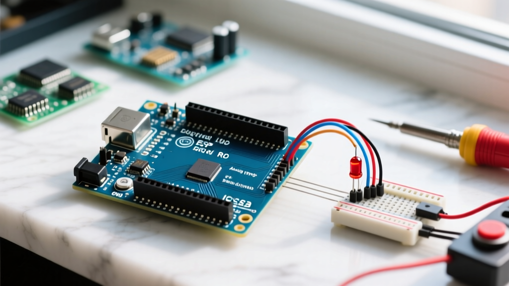

Introduction to the Arduino Uno R3 Architecture
The Arduino Uno R3 remains the undisputed workhorse of the maker community and educational labs worldwide. At its core lies the Microchip ATmega328P-PU microcontroller, clocked by a 16 MHz quartz crystal, providing a reliable and predictable execution environment for embedded projects. As of 2026, a genuine Arduino Uno R3 retails for approximately $27.50, while high-quality third-party clones utilizing the CH340 USB-to-Serial chip can be sourced for $12 to $15. Understanding the exact Arduino Uno R3 pin configuration is the critical first step before applying power to any external circuit. Misinterpreting voltage levels or current limits can instantly destroy the microcontroller's silicon die via latch-up or thermal runaway.
Decoding the Arduino Uno R3 Pin Layout
The physical headers on the Uno R3 are divided into three distinct functional zones: Power, Digital I/O, and Analog Inputs. Let us break down the electrical characteristics of each zone to ensure your first project is wired safely.
Power and Reference Headers
- 5V: Outputs the regulated 5V from the onboard NCP1117ST50T3G linear regulator (when powered via the barrel jack or Vin) or directly from the USB VBUS (when powered via USB). Warning: Drawing more than 400mA from this pin while using the barrel jack will overheat the regulator.
- 3.3V: A regulated 3.3V supply generated by an onboard LP2985 low-dropout regulator. Maximum continuous draw is strictly limited to 50mA.
- GND: Common ground references. There are three GND pins on the power header and two on the digital header. All are tied to the same ground plane.
- Vin: Accepts an unregulated input voltage (recommended 7V to 12V, absolute max 20V) to power the board via the onboard regulator. It also outputs the raw voltage if the board is powered via the DC barrel jack.
- IOREF: Provides the voltage reference for the microcontroller's I/O logic. On the Uno R3, this is hardwired to 5V. Shield designers use this pin to switch onboard level-shifters automatically.
Digital I/O and PWM Capabilities
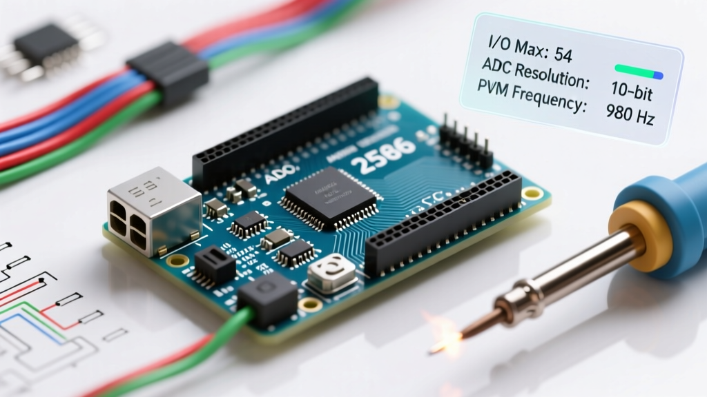
Pins 0 through 13 operate as standard digital inputs or outputs. They read HIGH (above 3.0V) or LOW (below 1.5V) and output either 0V or 5V. Six of these pins—specifically 3, 5, 6, 9, 10, and 11—are marked with a tilde (~). These are routed to the ATmega328P's internal hardware timers, enabling 8-bit Pulse Width Modulation (PWM) via the analogWrite() function at a default frequency of 490 Hz (pins 5 and 6 run at 980 Hz).
Crucial Note: Pins 0 (RX) and 1 (TX) are hardwired to the ATmega16U2 USB-to-Serial bridge. Attaching external circuits to these pins will interfere with USB communication and cause sketch upload failures.
Analog Inputs (A0 - A5)
The six analog pins (A0 through A5) route to the microcontroller's internal 10-bit Analog-to-Digital Converter (ADC). They map input voltages between 0V and 5V to integer values between 0 and 1023. These pins can also be addressed as standard digital I/O pins (14 through 19) if your project requires extra digital lines.
Pinout Quick Reference Matrix
| Pin Group | Identifiers | Voltage Level | Max Current per Pin | Primary Function |
|---|---|---|---|---|
| Digital I/O | 2, 4, 7, 8, 12, 13 | 0V / 5V | 20mA (Recommended) | Basic logic, buttons, relays |
| Digital PWM | 3, 5, 6, 9, 10, 11 | 0V / 5V (Duty Cycle) | 20mA (Recommended) | Motor speed, LED dimming |
| Serial UART | 0 (RX), 1 (TX) | 0V / 5V | 20mA (Recommended) | USB comms, GPS, Bluetooth |
| Analog In | A0, A1, A2, A3, A4, A5 | 0V to 5V | 20mA (As Digital) | Sensors, potentiometers |
Pre-Flight Setup: IDE 2.3+ and Driver Verification
Before wiring your first circuit, ensure your development environment is configured correctly. Download the latest Arduino IDE 2.3.x from the official website. If you are using a genuine Uno R3, the ATmega16U2 drivers are natively supported by Windows 11, macOS Sonoma, and modern Linux kernels. However, if you are using a budget clone board, you must manually install the CH340 drivers. You can find the official installation guide for CH340 adapters on the Arduino Support Portal.
Once installed, plug the board into a USB 2.0 or 3.0 port using a data-capable USB-B cable. A common beginner failure mode is using a charge-only cable, which lacks the internal D+ and D- data lines, resulting in the board powering on but failing to appear in the IDE's port menu.
First Project: Safe LED Wiring Using Pin 13
For your inaugural project, we will blink an external LED using Digital Pin 13. While Pin 13 features an onboard status LED (labeled 'L'), wiring an external component teaches you proper breadboard protocol and current-limiting calculations.
⚠️ Hardware Protection Warning: The ATmega328P datasheet specifies an absolute maximum DC current of 40mA per I/O pin, and a total VCC/GND package limit of 200mA. Exceeding 20mA per pin degrades the silicon over time. Always use a current-limiting resistor for LEDs.
Component List and Exact Specifications
- 1x Arduino Uno R3 (Genuine or Clone)
- 1x Standard 5mm Red LED (Forward Voltage: ~2.0V, Desired Current: 15mA)
- 1x 220Ω or 330Ω Carbon Film Resistor (1/4 Watt)
- 1x Half-size or Full-size Solderless Breadboard
- 2x Male-to-Male Jumper Wires (22 AWG stranded)
Step-by-Step Circuit Assembly
- Disconnect Power: Always unplug the USB cable before modifying your breadboard circuit to prevent accidental short circuits.
- Insert the Resistor: Place one leg of the 220Ω resistor into Pin 13 on the digital header. Insert the other leg into an empty row on the breadboard (e.g., Row 10, Column A).
- Insert the LED: Identify the LED's polarity. The longer leg is the Anode (+), and the shorter leg (with the flat edge on the plastic housing) is the Cathode (-). Insert the Anode into the same row as the resistor (Row 10, Column B).
- Complete the Ground Path: Insert the LED's Cathode into an adjacent row (Row 11, Column B). Use a jumper wire to connect Row 11 to any of the GND pins on the Arduino's power header.
- Verify Connections: Ensure no bare metal leads are touching adjacent rows, which would bypass the resistor and create a dead short.
Writing the Blink Sketch: Under the Hood
Open the Arduino IDE, navigate to File > Examples > 01.Basics > Blink, and verify the code matches the snippet below. We will explicitly define Pin 13 to ensure clarity.
// Define the physical Arduino Uno R3 pin connected to the LED
const int ledPin = 13;

void setup() {
  // Configure the pin's internal DDRB register as an OUTPUT
  pinMode(ledPin, OUTPUT);
}

void loop() {
  digitalWrite(ledPin, HIGH);  // Output 5V (Source current)
  delay(1000);                 // Halt execution for 1000ms
  digitalWrite(ledPin, LOW);   // Output 0V (Sink current)
  delay(1000);                 // Halt execution for 1000ms
}
Click the Upload button (right-pointing arrow). The 'TX' and 'RX' LEDs on the board will flicker rapidly as the compiled HEX file is transferred via the UART bootloader. Once complete, your external LED will blink at a precise 1Hz frequency.
Hardware Protection and Common Failure Modes
As you progress beyond simple LEDs, understanding how the Arduino Uno R3 protects itself—and where it fails—is vital for long-term project reliability. For deeper electrical theory on managing varying sensor voltages, consult the SparkFun Voltage Divider Tutorial to ensure you never feed more than 5V into the analog pins.
The 500mA USB Polyfuse
Located near the USB port is a resettable PTC polyfuse (often marked with a 'P' or '501'). If your external circuit draws more than 500mA from the 5V USB line, or if you accidentally short 5V to GND, this fuse will heat up and transition to a high-resistance state, cutting off power to protect your computer's USB motherboard port. Once the fault is removed, it takes approximately 2 to 5 minutes for the polyfuse to cool and reset automatically.
Overvoltage and Latch-up
The ATmega328P-PU is strictly a 5V logic device. Applying voltages greater than 5.5V to any digital or analog I/O pin will forward-bias the internal ESD protection diodes. If the current through these diodes exceeds their thermal limits, it triggers a destructive phenomenon known as CMOS latch-up, permanently shorting the pin to VCC or GND and requiring a microcontroller replacement. If you need to interface 3.3V sensors or 12V automotive signals, you must use optocouplers or bidirectional logic level shifters.
Authoritative References
For comprehensive schematics and advanced microcontroller datasheets, refer to the following official documentation:
- Official Arduino Uno Rev3 Hardware Documentation - Complete schematic, PCB layout, and technical specifications.
- Arduino Support: CH340 Driver Installation - Essential troubleshooting for third-party clone boards.
- SparkFun: Voltage Dividers - Critical theory for safely scaling analog sensor voltages to the Uno's ADC limits.