
The Great Divide: Navigating the Arduino Mega Pinout and Hardware Ecosystem
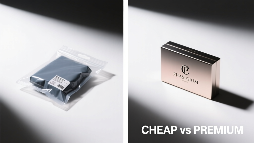
When your project outgrows the 14 digital pins of an Uno, the Arduino Mega pinout becomes your ultimate roadmap. Boasting 54 digital I/O pins, 16 analog inputs, and four hardware UARTs, the Mega 2560 is the undisputed workhorse for complex DIY builds, from CNC routers to automated greenhouse controllers. However, as you map out your wiring diagram, you will inevitably face a critical procurement decision: do you invest in the premium, official Arduino Mega 2560 Rev3 (priced around $48 in 2026), or do you opt for a budget CH340-based clone (often found for $14 to $18)?
While the silkscreen Arduino Mega pinout remains identical across both tiers, the underlying silicon, voltage regulation, and USB-to-serial architecture differ drastically. Understanding these hardware-level variations is crucial for preventing thermal throttling, communication dropouts, and shield incompatibilities in high-current applications.
The Definitive Arduino Mega Pinout Matrix
Before diving into the hardware comparison, let us establish the foundational I/O mapping. According to the official Arduino Mega 2560 documentation, the board utilizes the ATmega2560 microcontroller. Below is the structured breakdown of the pinout, including critical edge cases that frequently trip up intermediate makers.
| Function Category | Pin Numbers | Technical Notes & Edge Cases |
|---|---|---|
| Digital I/O | 0 to 53 | Pins 0 and 1 are shared with Hardware Serial0 (USB). Avoid using them for general I/O if serial debugging is required. |
| PWM Output | 2-13, 44-46 | 15 pins total. Default frequency is ~490Hz. Pins 4 and 13 share Timer0; altering their frequency breaks delay() and millis(). |
| Analog Inputs | A0 to A15 | 10-bit ADC resolution. Can be referenced as digital pins 54 through 69 in code. Aref pin accepts 0-5V max. |
| I2C Bus | 20 (SDA), 21 (SCL) | Rev3 Change: Older Rev1/Rev2 boards routed I2C to different pins. Modern shields expect SDA/SCL on 20/21 and the dedicated 8-pin header. |
| SPI Bus | 50 (MISO), 51 (MOSI), 52 (SCK), 53 (SS) | Also available on the 2x3 ICSP header. Pin 53 must be set as OUTPUT for the Mega to act as an SPI master, even if not physically used. |
| Hardware UART | 0-1, 14-15, 16-17, 18-19 | Serial, Serial1, Serial2, Serial3. Pins 14-19 are 5V tolerant and ideal for GPS modules or DMX512 transceivers. |
| External Interrupts | 2, 3, 18, 19, 20, 21 | Only these 6 pins support hardware interrupts (attachInterrupt()). Pin 2 is INT4, Pin 3 is INT5 on the Microchip ATmega2560 datasheet. |
Budget Clones vs. Premium Official: A Hardware Deep Dive
Tracing the Arduino Mega pinout on a PCB reveals that while the traces match, the components populating them tell a different story. Here is where the budget vs. premium debate moves from philosophical to strictly electrical.
1. Voltage Regulation and Thermal Failure Modes
The most dangerous divergence between premium and budget boards lies in the 5V linear voltage regulator (LDO). When you power your Mega via the barrel jack or VIN pin, this component steps down the input voltage (typically 7V-12V) to a stable 5V for the logic and shields.
- Premium (Official Rev3): Arduino utilizes an ON Semiconductor NCP1117ST50T3G. This robust LDO features integrated thermal shutdown and can safely dissipate the heat generated by stepping down 9V to 5V at continuous currents up to 600mA-800mA (with adequate copper pour acting as a heatsink).
- Budget (Generic Clones): Most $15 clones utilize generic, unbranded AMS1117-5.0 LDOs. These components often lack reliable thermal protection and suffer from high dropout voltages. If your project includes a motor shield or an LCD backlight drawing more than 300mA from the 5V pin, the clone's LDO will overheat, causing severe voltage sag. This leads to ATmega2560 brownouts, random memory corruption, and erratic I/O behavior.
2. The USB-to-Serial Interface: ATmega16U2 vs. CH340G
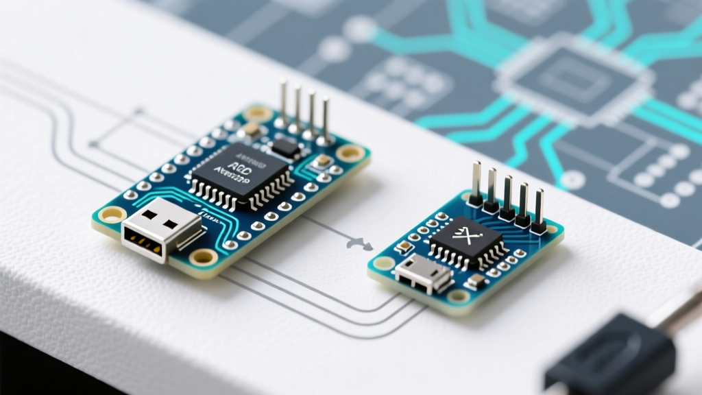
The official board uses a dedicated ATmega16U2 microcontroller programmed as a USB-to-serial converter. Budget clones almost universally use the WCH CH340G chip to cut costs.
Expert Insight: The CH340G is actually a highly reliable, plug-and-play solution on modern Windows 11 and macOS environments. However, the premium ATmega16U2 allows you to reflash the 16U2 via the onboard ICSP header to turn the Mega into a native USB HID device (like a custom MIDI controller or macro keyboard) without needing a secondary microcontroller. If your project requires native USB HID capabilities, the premium board is mandatory.
3. Build Quality, Flux Residue, and Header Soldering
When sourcing from the official Arduino store, you receive a board with automated, high-precision wave soldering and ultrasonic cleaning. Budget clones frequently exhibit visible flux residue, cold solder joints on the dual-row female headers, and misaligned USB-B ports. Over time, the mechanical stress of plugging and unplugging heavy sensor cables can cause the poorly soldered headers on clones to lift the copper pads directly off the FR4 fiberglass substrate.
Advanced Pinout Edge Cases and Routing Rules
Regardless of whether you choose a clone or a premium board, mastering the Arduino Mega pinout requires navigating a few microcontroller-level quirks inherent to the ATmega2560 architecture.
- The I2C Pull-Up Resistor Trap: Unlike the Uno, the official Mega 2560 Rev3 does not have internal pull-up resistors on the SDA (20) and SCL (21) lines. If you are connecting raw I2C sensors (like the BME280 or MPU6050) without a dedicated breakout board that includes them, you must manually solder 4.7kΩ pull-up resistors to the 5V line, or the bus will fail to initialize.
- SPI Pin Routing Conflicts: Many makers attempt to use pins 50-53 for standard digital I/O while simultaneously using the ICSP header for an SPI display. While electrically possible, doing so often causes phase conflicts if the software library assumes the standard hardware SPI pins are dedicated. Always reserve 50-53 exclusively for SPI bus management.
- ADC Crosstalk on Analog Pins: When reading high-impedance analog sensors (above 10kΩ output impedance) on adjacent analog pins (e.g., A0 and A1), the internal sample-and-hold capacitor does not have enough time to charge fully, causing 'ghosting' or crosstalk between readings. Insert a
analogRead()dummy read and a 10msdelay()between critical analog pin polls to stabilize the ADC.
The Decision Framework: Which Board Should You Deploy?
Do not default to the cheapest option, but do not overpay for premium branding when a clone will suffice. Use this framework for your 2026 project planning:
Choose the Budget Clone ($14 - $18) When:
- You are building a low-power IoT node powered entirely via the USB port (bypassing the onboard LDO).
- The project is for educational prototyping, classroom deployments, or temporary proof-of-concept testing.
- Your shield stack draws less than 200mA total from the 5V rail (e.g., basic relay modules and low-power I2C sensors).
Choose the Premium Official Rev3 ($45 - $50) When:
- You are powering the board via a 9V/12V barrel jack to run high-current shields (motor drivers, heated bed MOSFETs for 3D printers, or multiple servos).
- The project requires native USB HID capabilities via 16U2 reflashing.
- The installation is permanent, enclosed in a chassis with limited airflow, and requires the thermal safety nets of premium voltage regulators.
- You are integrating commercial, high-density shields that rely on the exact mechanical tolerance of premium-soldered female headers.
Final Thoughts on Scaling Your Projects
The Arduino Mega pinout offers unparalleled flexibility for complex DIY electronics, but the physical board you choose dictates the reliability of that flexibility. By understanding the thermal limits of clone voltage regulators and the specific interrupt mappings of the ATmega2560, you can engineer systems that survive long beyond the prototyping phase. Match your hardware procurement to your project's electrical demands, and your Mega-based builds will operate flawlessly for years to come.