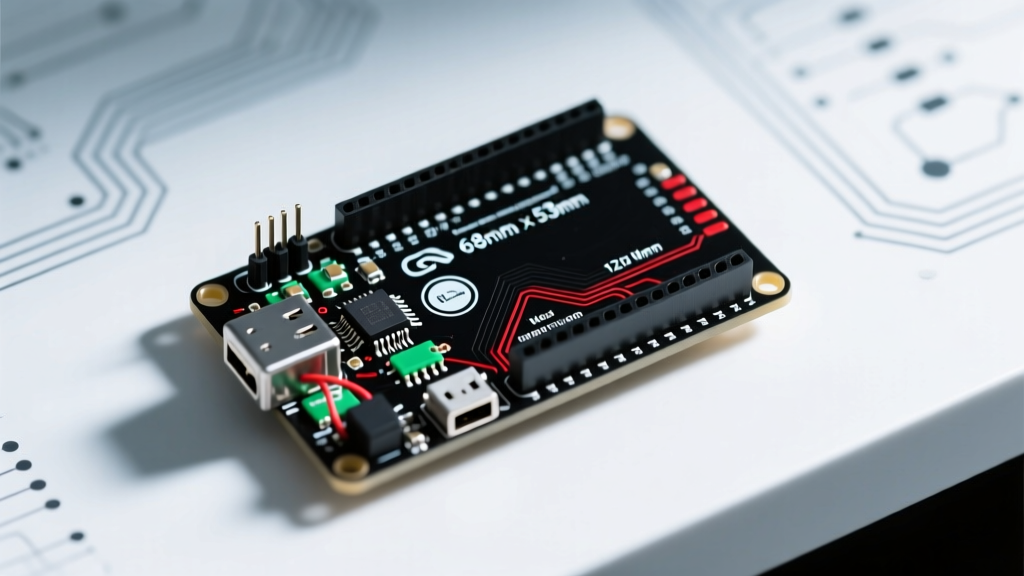

Decoding the Exact Arduino Uno R3 Dimensions
When you unbox your first microcontroller, the immediate impulse is to plug it in and start coding. However, as you transition from a messy desk prototype to a permanent installation, the physical constraints of the board become your biggest hurdle. Understanding the precise Arduino Uno R3 dimensions is the critical first step in designing custom enclosures, selecting the right breadboards, and avoiding mechanical stress on the PCB.
According to the Arduino Official Documentation, the Uno R3 follows a standardized footprint that has remained largely unchanged since its release. Yet, millimeter-level variations between genuine boards and third-party clones can derail a 3D-printed enclosure design. Below is the definitive measurement matrix you need for your setup phase.
| Parameter | Metric (mm) | Imperial (inches) | Design Notes & Tolerances |
|---|---|---|---|
| PCB Length | 68.58 mm | 2.70" | Excludes USB-B port overhang |
| PCB Width | 53.34 mm | 2.10" | Max width at the power headers |
| USB-B Port Overhang | 16.00 mm | 0.63" | Extends past the left PCB edge |
| DC Barrel Jack Overhang | 9.50 mm | 0.37" | Extends past the bottom PCB edge |
| Mounting Hole Diameter | 3.20 mm | 0.125" | Fits standard M3 screws |
| Max Component Height (Top) | 11.00 mm | 0.43" | Measured from PCB surface to USB port top |
| Header Pin Height | 8.50 mm | 0.33" | Female header plastic housing height |
The "Gotcha": Mounting Hole Asymmetry
Here is an edge case that ruins countless first-time 3D printed enclosures: the mounting holes are not a perfect rectangle. On a genuine Arduino Uno R3, the bottom-right mounting hole (near the ATmega16U2 chip) is offset by exactly 0.1 inches (2.54 mm) toward the center of the board. The Arduino engineering team implemented this deliberate asymmetry to prevent users from inserting custom shields upside down.
Expert Warning: Many budget clone boards manufactured in 2025 and 2026 "correct" this offset, placing all four holes in a perfect symmetrical grid. If you design an enclosure baseplate using the genuine Arduino CAD files but purchase a generic clone, your bottom-right standoff will not align. Always measure your specific board with digital calipers before finalizing your enclosure STL files.
The Setup Phase: Breadboarding Constraints
For your first project, you will likely pair the Uno R3 with a standard 830-point solderless breadboard. The physical dimensions of the Uno dictate how you manage your workspace.
- The Width Problem: A standard 830-point breadboard is roughly 65 mm wide. The Uno R3 is 53.34 mm wide. If you straddle the board across the center power trench, you are left with only ~5.8 mm of clearance on either side for jumper wires. This is too tight for standard 2.54mm Dupont connectors.
- The Solution: Do not mount the Uno directly on the breadboard for your first permanent setup. Instead, place the Uno adjacent to the breadboard and use male-to-male jumper wires. Alternatively, invest in an "Arduino Breadboard Shield" or a specialized side-car breadboard that snaps into the Uno's female headers, extending the prototyping area outward without compromising the USB connection angle.
Designing Your First Custom Enclosure
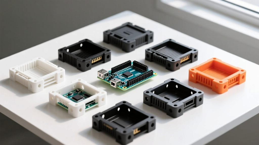
Moving from a breadboard to a custom enclosure is a rite of passage. Whether you are using FDM 3D printing or laser-cut acrylic, the Arduino Uno R3 dimensions require specific clearance tolerances.
Step 1: Calculate Internal Z-Height Clearance
The PCB itself is 1.6mm thick (standard FR4). The tallest components on the top are the USB-B port (11mm) and the female headers (8.5mm). If you route jumper wires out of the top of the enclosure, you must account for the Dupont connector housings, which add another 7mm to 9mm of height. Design your enclosure with a minimum internal Z-height of 22mm to allow wires to bend naturally without stressing the header solder joints.
Step 2: Port Cutout Tolerances
When cutting holes for the USB-B and DC barrel jack, use the following dimensions for your CAD software:
- USB-B Cutout: 13.0 mm x 12.0 mm (The port is ~12x11mm, but FDM 3D printing requires a +0.5mm tolerance on all sides to account for plastic shrinkage and layer shifting).
- DC Jack Cutout: 10.0 mm diameter circle (The jack is 9mm, but the extra 1mm allows for easy insertion of the power adapter without scraping the enclosure walls).
- Reset Button Access: Do not forget a 6mm diameter hole directly above the reset switch. The switch sits 5mm above the PCB, making it inaccessible if your enclosure lid is flush.
For a deeper dive into managing manufacturing tolerances in desktop fabrication, refer to this comprehensive guide on 3D printing tolerances and clearances.
Mounting Hardware: What to Buy in 2026
Never screw an Arduino directly into a plastic or metal chassis. The pressure will crack the PCB traces around the mounting holes, and metal chassis will cause immediate short circuits on the bottom solder joints. You must use standoffs.
For a professional setup, source the following hardware (easily found in a $12 M3 brass standoff assortment kit on Amazon or Mouser):
- Standoffs: M3 x 10mm Female-Female Brass Hex Standoffs. (10mm provides enough bottom clearance to ensure the bottom-layer copper traces and through-hole leads never touch your chassis).
- Screws: M3 x 8mm Pan Head Machine Screws. (Pan head is crucial; flat/countersunk heads will wedge into the 3.2mm mounting holes and crack the fiberglass PCB when tightened).
- Isolation Washers: If using a metal enclosure, place a nylon M3 washer between the brass standoff and the metal chassis to prevent ground loops.
Critical Failure Modes to Avoid
When designing around the Arduino Uno R3 dimensions, beginners frequently encounter three mechanical failure modes. Avoid these to ensure your first project survives long-term deployment.
1. Shearing the USB-B Port
The USB-B connector on the Uno R3 is through-hole soldered, but it is highly susceptible to lateral shearing forces. If your 3D printed enclosure requires you to "snap" the board into a tight slot, the friction against the USB port housing can rip the solder pads right off the PCB. Always design enclosures with a drop-in top-down assembly, securing the board via the four M3 mounting holes rather than relying on friction-fit edge rails.
2. The ICSP Header Interference
The 2x3 ICSP header (used for programming the ATmega328P directly) is located near the center-right of the board. It extends 8.5mm upward. If you design a multi-layer enclosure or stack a custom shield on top, ensure you leave a 10mm x 15mm cutout in the shield PCB or enclosure lid to maintain access to this header for future firmware recovery.
3. Clone Board USB-C Variations
While the classic Uno R3 uses the bulky USB-B connector, several 2025/2026 "Uno R3 Compatible" boards from manufacturers like Elegoo and Keyestudio have swapped to USB-C. While the PCB length and width remain identical (68.58 x 53.34 mm), the USB-C port overhang is significantly shorter (only ~7mm instead of 16mm). If you are buying a modern clone, verify the USB port type before finalizing your enclosure's side-wall cutouts.
By mastering the exact Arduino Uno R3 dimensions and accounting for real-world manufacturing tolerances, your transition from a messy desk setup to a robust, enclosed prototype will be seamless. Always measure twice, print once, and respect the asymmetrical mounting holes.