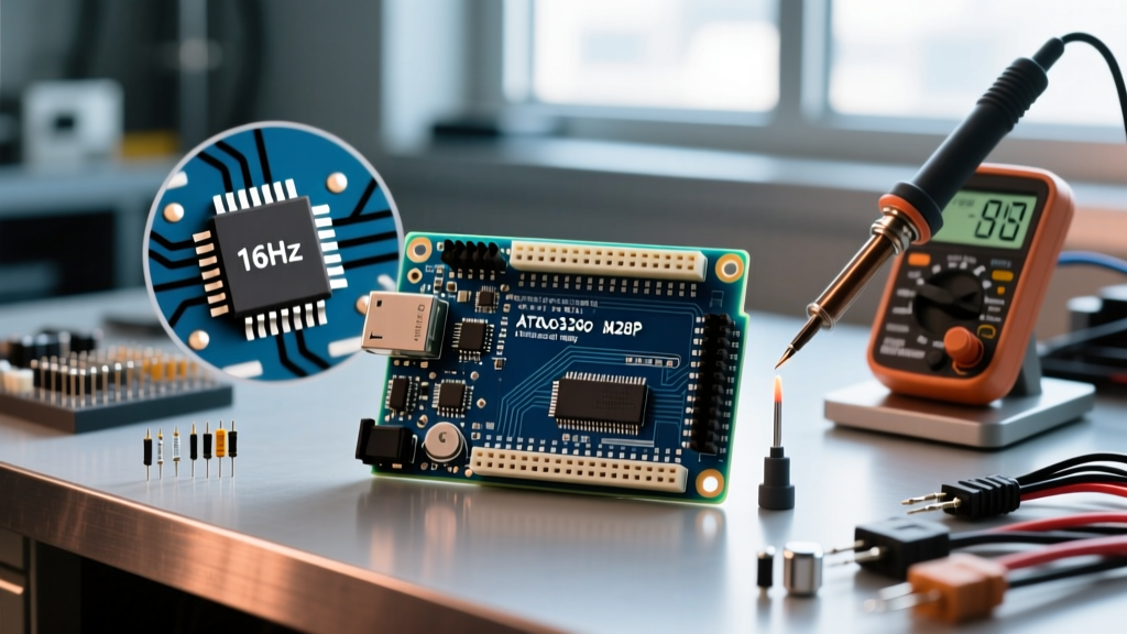

The Physical Footprint: Exact Dimensions of the Arduino Mega 2560
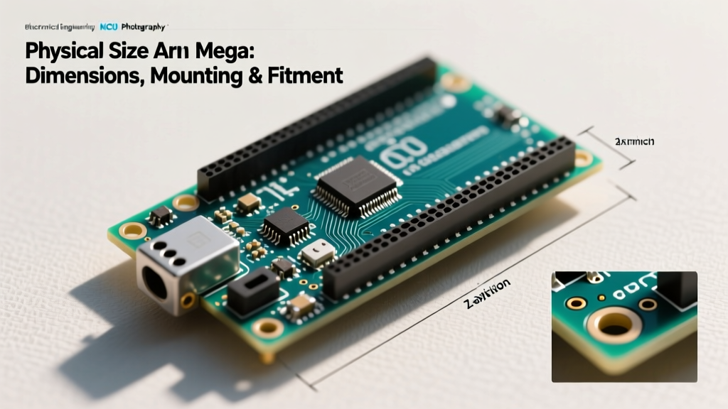
When designing control panels, robotics chassis, or custom 3D-printed enclosures, the physical size of Arduino Mega boards dictates your entire mechanical layout. Unlike the compact Nano or the square-footprint Uno, the Mega 2560 Rev3 utilizes an elongated rectangular form factor to accommodate its massive I/O count and dual-microcontroller architecture. Understanding its exact millimeter specifications is the first step in avoiding costly fitment failures.
Quick Spec Card: Arduino Mega 2560 Rev3
• Length: 101.52 mm (4.0 inches)
• Width: 53.3 mm (2.1 inches)
• PCB Thickness: 1.6 mm (Standard FR4)
• Weight: ~37 grams (board only)
• Header Pitch: 2.54 mm (0.1 inches)
A critical edge case that catches many enclosure designers off guard is the component overhang. The USB Type-B connector and the DC barrel jack extend slightly past the edge of the PCB. If you are designing a flush-mount enclosure where the PCB edge meets a wall, you must add a minimum 1.5 mm relief cutout on the Y-axis to accommodate the metal shielding of the USB port and the plastic housing of the barrel jack.
The Mounting Hole Anomaly: A Trap for Enclosure Designers
The most notorious physical quirk regarding the size of Arduino Mega is its asymmetrical mounting hole layout. While the Arduino Uno features a perfectly symmetrical rectangular mounting pattern, the Mega does not. This is not a manufacturing defect; it is a deliberate PCB routing compromise to allow high-speed traces from the ATmega2560 to reach the ATmega16U2 USB-to-Serial controller without crossing split planes.
If you are CNC machining an aluminum backplate or designing an SLA resin enclosure, you must use the exact coordinates below. Assuming the top-left mounting hole is at coordinate (0,0):
| Mounting Hole | X-Axis Distance | Y-Axis Distance | Physical Location |
|---|---|---|---|
| Hole 1 (Top Left) | 0 mm | 0 mm | Adjacent to DC Barrel Jack |
| Hole 2 (Top Right) | 89.9 mm (3.54") | 0 mm | Adjacent to Reset Button |
| Hole 3 (Bottom Left) | 0 mm | 86.4 mm (3.40") | Near Analog Ground Pin |
| Hole 4 (Bottom Right) | 95.9 mm (3.78") | 92.4 mm (3.64") | Offset outward near Digital Pin 22 |
Pro Tip: The bottom-right hole is offset outward by 6 mm on the X-axis and 6 mm on the Y-axis compared to the top-right hole. When designing 3D printed standoffs, always model the standoffs as individual cylinders rather than a unified raised platform to account for this asymmetry. According to the official Arduino Mega 2560 documentation, the holes are designed for M3 (3mm) screws, but using M2.5 screws with silicone washers provides better vibration dampening in motor-heavy robotics projects.
Z-Axis Clearance: Managing Height with Shields and Wiring
The X-Y dimensions only tell half the story. The Z-axis (height) of the Arduino Mega is highly variable depending on your header selection and shield stacking. Managing this vertical space is crucial for enclosure lid clearance.
Base Component Heights
- PCB Base: 1.6 mm
- Standard Female Headers: 8.5 mm
- Tallest SMD Components (USB/ICSP): ~11.0 mm
- Total Base Height (No Shield): ~12.6 mm
Shield Stacking and the 'Wobble' Factor
When you plug in a standard Arduino shield, the male pins on the shield are typically 11.5 mm long. This brings the total height of a Mega with a single shield to approximately 28 mm to 30 mm. However, because of the Mega's extended length, shields often suffer from lateral 'wobble' at the bottom-right corner. This occurs because many third-party shield manufacturers only include three sets of stacking headers to save costs, ignoring the Mega's fourth (offset) mounting hole. To fix this in custom rigs, use an M3 nylon standoff to bridge the gap between the Mega's bottom-right hole and the shield, ensuring rigid tactile feedback when pressing shield-mounted buttons.
Size of Arduino Mega vs. Alternatives: Spatial Trade-offs
Is the Mega too big for your current chassis? As of 2026, the market offers several alternatives if the standard 101.52 mm length is prohibitive. Genuine boards retail around $48, while high-quality clones (like Elegoo or HiLetgo) sit in the $16–$18 range, making spatial experimentation affordable.
| Board Model | Dimensions (L x W) | Mounting Holes | Best Use Case |
|---|---|---|---|
| Arduino Mega 2560 Rev3 | 101.5 x 53.3 mm | 4 (Asymmetrical) | Benchtop prototyping, 3D printer controllers, standard enclosures. |
| Arduino Uno R4 Minima | 68.6 x 53.4 mm | 4 (Symmetrical) | Compact panels where 54 I/O pins are not required. |
| Mega 2560 Pro Mini (Clone) | 65.0 x 38.0 mm | 2 or 4 (Varies) | Embedded drones, tight 3D printed robotics, permanent soldered installs. |
| Arduino Nano Every | 45.0 x 18.0 mm | 2 | Micro-sensors, wearable tech, breadboard-only prototypes. |
The Mega Pro Mini (often produced by clone manufacturers like RobotDyn or HiLetgo) is the ultimate workaround for the Mega's size constraints. It strips away the USB-B port, DC barrel jack, and bulky female headers, shrinking the footprint by nearly 40% while retaining the ATmega2560 chip. The trade-off is that you must wire a custom FTDI USB-to-Serial adapter for programming and manage your own 5V/3.3V power regulation.
Real-World Enclosure Fitment and 3D Printing Tolerances
Designing a custom enclosure for the Mega requires compensating for manufacturing tolerances, particularly if you are using FDM (Fused Deposition Modeling) 3D printing. According to the Prusa Research Dimensional Accuracy Guide, FDM printers typically exhibit a dimensional variance of ±0.2 mm on the X and Y axes due to filament shrinkage and belt tension.
Actionable CAD Guidelines for Mega Enclosures
- The 0.25 mm Clearance Rule: Never model your enclosure cavity at exactly 101.52 x 53.3 mm. Add a 0.25 mm offset to all internal walls. A cavity sized 102.0 x 53.8 mm ensures the board drops in without requiring sanding.
- Heat-Set Inserts over Self-Tapping: Do not self-tap screws directly into PLA or PETG standoffs; the asymmetrical torque of the Mega's offset bottom-right hole will strip the plastic over time. Instead, design your standoffs with 4.0 mm pilot holes and press in M3 x 5.7 mm brass heat-set inserts using a soldering iron set to 280°C.
- Header Cutouts: If your enclosure wraps around the sides to protect the pins, remember that the Mega features double-row female headers on the left side (Digital Pins 22-53) and a double-row on the right (Analog/Power). Your CAD cutouts must be 5.08 mm wide (two standard 2.54mm pitches) on these specific edges, not the standard 2.54 mm used on the Uno.
Frequently Asked Questions
Will an Arduino Uno enclosure fit an Arduino Mega?
No. While the width (53.3 mm) and the top-left mounting hole placement are identical between the Uno and the Mega, the Mega is 33 mm longer (101.52 mm vs 68.6 mm). Furthermore, the Mega's bottom mounting holes are in completely different locations. You must use an enclosure specifically tooled for the Mega 2560 form factor.
Does the size of the Arduino Mega affect its performance?
Physically, the larger PCB size actually benefits the Mega's performance in high-noise environments. The extra surface area allows engineers to route ground planes more effectively and separate the high-current digital switching traces from the sensitive analog-to-digital converter (ADC) reference lines. This physical separation results in slightly cleaner analog readings compared to tightly packed clone boards.
What is the maximum wire gauge the Mega's screw shields can handle?
While not a property of the Mega itself, when utilizing the board's size to mount heavy-duty screw terminal shields, the physical pitch of the terminals usually limits you to 14 AWG to 12 AWG wire (roughly 2.0 to 2.5 mm diameter). Attempting to force 10 AWG wire into standard 5.08mm pitch terminal blocks will cause the metal clamp to bind and fail to make proper contact with the stranded copper.