
The Global Search for the Datenblatt
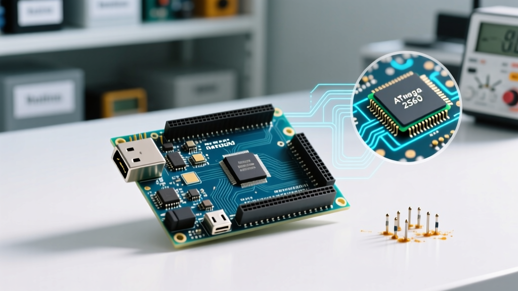
Whether you are an automation engineer in Berlin searching for the Arduino Mega 2560 Datenblatt or a robotics hobbyist in New York looking for the official English datasheet, the underlying hardware realities of Microchip’s ATmega2560 microcontroller remain universal. The Arduino Mega 2560 has been the undisputed heavyweight champion of the maker ecosystem for over a decade, serving as the brain for everything from Prusa 3D printers (via the Rambo/Einsy boards derived from its architecture) to complex CNC routers.
However, simply reading the basic pinout diagram is not enough for professional-grade deployments. In this feature deep dive, we move beyond the superficial marketing specs and decode the actual silicon limitations, power distribution edge cases, and memory architectures that define the Mega 2560 in 2026.
Silicon Core: ATmega2560 vs. ATmega328P
The most common point of confusion when transitioning from an Uno to a Mega is assuming the underlying architecture is identical, just "larger." While both belong to the 8-bit AVR family, the ATmega2560 introduces a fundamentally different memory addressing scheme and peripheral layout. Below is a strict hardware comparison matrix.
| Specification | Arduino Uno (ATmega328P) | Arduino Mega 2560 (ATmega2560) |
|---|---|---|
| Flash Memory | 32 KB | 256 KB |
| SRAM | 2 KB | 8 KB |
| EEPROM | 1 KB | 4 KB |
| Digital I/O Pins | 14 (6 PWM) | 54 (15 PWM) |
| Analog Input Pins | 6 (10-bit ADC) | 16 (10-bit ADC) |
| Hardware UARTs | 1 | 4 |
| Timer Architecture | Two 8-bit, One 16-bit | Two 8-bit, Four 16-bit |
Power Architecture and Thermal Failure Modes
The most frequent cause of catastrophic failure in Mega 2560 deployments is misunderstanding the onboard voltage regulator's thermal limits. The board utilizes a linear regulator (typically an NCP1117ST50T3G or equivalent 1A LDO in a SOT-223 package) to drop the barrel jack input voltage down to 5V.
CRITICAL THERMAL WARNING: If you supply 12V via the barrel jack and draw 250mA from the 5V pin, the regulator must dissipate 1.75W of heat ((12V - 5V) * 0.25A). Without active cooling or a massive copper pour heatsink, the junction temperature will exceed 150°C in under 60 seconds, triggering thermal shutdown or permanently destroying the silicon.
The 5V and 3.3V Rail Limits
- 5V Rail via USB: Limited by the USB host port or the onboard polyfuse (typically 500mA resettable PTC). Real-world safe continuous draw is 400mA.
- 5V Rail via Barrel Jack: Dictated by the LDO thermal envelope. Keep current draw under 200mA if input voltage exceeds 9V.
- 3.3V Rail: Generated by an onboard LP2985 or similar LDO fed from the 5V rail. The absolute maximum current draw on the 3.3V pin is 150mA. Exceeding this will cause the 3.3V rail to sag, leading to brownouts in attached ESP32 or RF modules.
- Per-I/O Pin Limit: 40mA absolute maximum, but 20mA is the recommended continuous limit to prevent electromigration and port degradation over time.
Memory Map and Bootloader Overhead
When engineers consult the official Microchip ATmega2560 datasheet, the memory map reveals critical constraints for advanced firmware development.
The 256KB of Flash memory is not entirely available for your sketch. The Arduino Mega 2560 ships with a bootloader (historically STK500v2, though modern iterations often use optimized variants) that occupies the upper 8KB of the flash space. This leaves exactly 248KB for user application code. If you are compiling massive lookup tables or embedding compressed audio assets, you must monitor the compiler output to ensure you do not overwrite the bootloader section, which will brick the board's ability to auto-program via USB.
Furthermore, the 8KB of SRAM is split. The first 224 bytes are reserved for I/O registers and extended I/O. The remaining 7.8KB is available for heap and stack operations. When utilizing libraries like U8g2 for large graphical OLED displays, a single full-screen frame buffer can consume 1KB+ of SRAM, rapidly leading to stack collisions if not managed with direct-to-display rendering techniques.
Timer Architecture and PWM Resolution
The Mega 2560’s timer setup is vastly superior to the Uno, but it introduces complexity regarding pin mapping. The board features six timers:
- Timer 0 (8-bit): Hardcoded by the Arduino core to drive
millis(),delay(), andmicros(). Never alter the prescaler on Timer 0 unless you are writing bare-metal C and providing your own timing interrupts. - Timer 1, 3, 4, 5 (16-bit): The workhorses for high-resolution PWM. These can be configured for Phase and Frequency Correct PWM, ideal for driving BLDC motors or high-fidelity audio DACs.
- Timer 2 (8-bit): Often used for tone generation or secondary asynchronous timing.
Because the 15 PWM pins are distributed unevenly across these timers, attaching a servo library (which hijacks a 16-bit timer) to specific pins will disable PWM on other seemingly unrelated pins sharing that same timer block. Always cross-reference the Arduino Mega 2560 hardware documentation timer-to-pin mapping chart before finalizing your PCB shield design.
Communication Interfaces and the I2C Pull-Up Edge Case
The Mega 2560 exposes four hardware UARTs, one SPI bus, and one I2C bus. However, the I2C implementation contains a notorious hardware trap that catches many engineers off guard.
The I2C pins (SDA on Pin 20, SCL on Pin 21) feature onboard 4.7kΩ pull-up resistors tied directly to the 5V rail. If you connect a modern 3.3V I2C sensor (like a BME280 or an MPU6050) directly to these pins, the 5V pull-ups will backfeed current into the sensor's internal protection diodes, eventually frying the 3.3V logic. Solution: You must either use a bidirectional logic level shifter (like a BSS138 MOSFET-based module) or physically cut the 5V pull-up traces on the Mega and wire external 3.3V pull-ups if your entire I2C bus operates at 3.3V.
Sourcing in 2026: Genuine vs. Clone Boards
The supply chain for AVR microcontrollers has stabilized significantly by 2026, but the market remains flooded with clone boards. Understanding the differences is vital for industrial versus hobbyist deployments.
USB-to-Serial Chip Differences
- Genuine Boards ($45 - $55 USD): Utilize the ATmega16U2 microcontroller as a dedicated USB-to-Serial bridge. This allows the Mega to be recognized natively as a standard serial port on all operating systems without third-party drivers. It also supports reprogramming the 16U2 via LUFA to make the Mega act as a native USB HID device (keyboard/mouse).
- Clone Boards ($12 - $18 USD): Overwhelmingly use the CH340C (or older CH340G) chip from WCH. The CH340C is dominant in 2026 because it integrates the crystal oscillator internally, reducing BOM costs and board footprint. However, it requires specific kernel drivers on older Windows and macOS environments, and it does not support native USB HID emulation.
Summary
Decoding the Arduino Mega 2560 Datenblatt is about looking past the sheer number of pins and understanding the electrical and architectural boundaries of the ATmega2560. By respecting the thermal limits of the linear regulator, managing the 8KB SRAM ceiling, avoiding the 5V I2C pull-up trap, and selecting the correct USB-Serial bridge for your deployment environment, the Mega 2560 remains an incredibly robust, high-I/O platform for complex electromechanical projects.