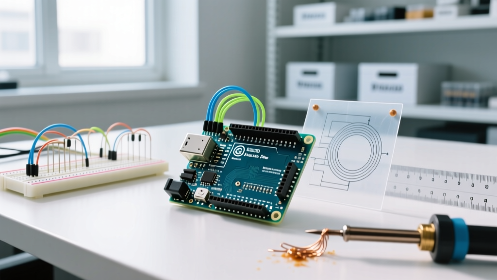

The Anatomy of the Arduino Uno Pinout
Whether you are working with the classic ATmega328P-based Uno Rev3 or the modern ARM-based Uno R4 Minima, understanding the physical interface of your microcontroller is the most critical step in electronics design. The Arduino Uno pins serve as the bridge between your code and the physical world, handling everything from reading temperature sensors to driving high-current relays. In 2026, while newer platforms like the ESP32 dominate IoT, the Uno remains the undisputed king of educational and prototyping environments due to its robust 5V logic tolerance and forgiving pin architecture.
This guide bypasses the generic overviews and dives deep into the electrical realities, current limitations, and hidden quirks of the Uno's pinout. Before wiring your first breadboard, you must understand what these pins can actually handle.
Power Pins: The Lifeblood and Its Limits
Beginners often treat the power rails as infinite sources of current, leading to fried voltage regulators and bricked boards. The Uno's power header consists of several critical pins:
- 5V: This pin outputs the regulated 5V used by the microcontroller. If powered via USB, it is limited by the USB host or the onboard polyfuse (typically 500mA). If powered via the barrel jack, it is limited by the onboard NCP1117 voltage regulator. Expert Warning: Drawing more than 400mA from the 5V pin while supplying 9V to the barrel jack will cause the regulator to overheat and trigger thermal shutdown.
- 3.3V: A regulated 3.3V output generated by an onboard step-down converter. It is strictly limited to 50mA on the Rev3. Use this only for low-power sensors (like the MPU6050) or as a logic reference, never for powering motors.
- GND (Ground): There are three GND pins on the power header and one near digital pin 8. They are all tied to the same ground plane. Always use a common ground when connecting external power supplies to your Uno.
- Vin (Voltage In): Connect an unregulated power supply (7V to 12V recommended) here to bypass the barrel jack. It feeds directly into the onboard 5V regulator.
- IOREF: Provides the voltage reference the microcontroller operates at (5V on the Uno). Shields use this pin to adapt their logic level shifting circuitry automatically.
Digital I/O Pins: The Workhorses
The Uno features 14 digital I/O pins (labeled 0 through 13). Each pin operates at 5V logic and can be configured as an INPUT, OUTPUT, or INPUT_PULLUP using standard Arduino functions. According to the Arduino Digital Pins Foundation Guide, the ATmega328P has an absolute maximum current rating of 40mA per I/O pin. However, to ensure long-term reliability and prevent silicon degradation, you should never exceed 20mA per pin. Furthermore, the combined total current sourced or sunk across all VCC and GND pins must not exceed 200mA.
The PWM Pins (The Tilde '~' Marking)
Pins marked with a tilde (~) — specifically 3, 5, 6, 9, 10, and 11 — support Pulse Width Modulation (PWM). This allows you to simulate analog output by rapidly toggling the pin HIGH and LOW. This is essential for dimming LEDs or controlling servo motors.
Critical PWM Frequency Detail: Not all PWM pins are created equal. Pins 5 and 6 operate at a default frequency of 980Hz, while pins 3, 9, 10, and 11 operate at 490Hz. If you are building an audio synthesis project or driving certain types of DC motors, this frequency discrepancy will cause audible whining or uneven motor response. For audio, always route your signal through pins 5 or 6. For deeper insights, refer to SparkFun's PWM Tutorial.
Analog Input Pins: Reading the Real World
Pins A0 through A5 are connected to the microcontroller's internal Analog-to-Digital Converter (ADC). The Uno's ADC is 10-bit, meaning it maps input voltages between 0V and 5V into integer values between 0 and 1023. This gives you a resolution of approximately 4.9mV per step ($5.0V / 1024$).
When wiring analog sensors like potentiometers or photoresistors, keep your wires short. High-impedance analog circuits act as antennas, picking up 50Hz/60Hz mains hum from your environment. If your analog readings are jittery, add a 0.1µF ceramic capacitor between the analog input pin and GND to filter out high-frequency noise.
Note: Analog pins A0-A5 can also be used as standard digital I/O pins if you run out of digital pins. Simply reference them in code as pinMode(A0, OUTPUT).
Communication Protocol Pins
Modern electronics rely on standardized communication buses. The Uno breaks these out across specific pins:
- UART (Serial): Pins 0 (RX) and 1 (TX) handle TTL serial communication. Failure Mode: Because these pins are shared with the USB-to-Serial chip, connecting external devices here will cause code upload failures and erratic Serial Monitor output. Always disconnect pins 0 and 1 when flashing new code.
- I2C (TWI): Located on A4 (SDA) and A5 (SCL). The Uno R4 and newer Rev3 boards also include dedicated SDA/SCL pins near the AREF pin for shield compatibility. I2C requires external 4.7kΩ pull-up resistors on both lines if your sensor breakout board doesn't include them.
- SPI: Found on 10 (SS), 11 (MOSI), 12 (MISO), and 13 (SCK). SPI is vastly faster than I2C and is the standard protocol for driving TFT displays and SD card modules.
Comprehensive Arduino Uno Pinout Cheat Sheet
Keep this matrix handy when designing your 2026 project schematics. For the official hardware schematics and tolerance sheets, consult the Arduino Uno Rev3 Documentation.
| Pin Category | Pin Numbers | Primary Function | Special Notes & Constraints |
|---|---|---|---|
| Digital I/O | 2, 4, 7, 8, 12, 13 | Standard Digital Read/Write | Pin 13 has an onboard LED tied to it; avoid using for sensitive inputs. |
| PWM Output | 3, 5, 6, 9, 10, 11 | Analog Simulation (PWM) | Pins 5 & 6 run at 980Hz; others run at 490Hz. |
| Serial (UART) | 0 (RX), 1 (TX) | USB & TTL Serial Comms | Disconnect during firmware uploads to prevent errors. |
| SPI Bus | 10, 11, 12, 13 | High-Speed Peripherals | Pin 10 must remain OUTPUT for Uno to act as SPI Master. |
| Analog In | A0, A1, A2, A3, A4, A5 | 10-bit ADC (0-1023) | A4/A5 double as I2C (SDA/SCL). 4.9mV resolution. |
| External Int. | 2 (INT0), 3 (INT1) | Hardware Interrupts | Use for rotary encoders or critical timing triggers. |
Common Beginner Mistakes and Troubleshooting
1. The Floating Pin Problem
If you configure a pin as INPUT and leave it unconnected, it becomes a 'floating pin.' It will pick up electromagnetic interference, causing digitalRead() to rapidly flip between HIGH and LOW. The Fix: Always use INPUT_PULLUP in your code. This engages the microcontroller's internal 20kΩ-50kΩ pull-up resistor, defaulting the pin to HIGH and pulling it cleanly to LOW when grounded by a button.
2. Powering Inductive Loads Directly
Never connect a relay coil, solenoid, or DC motor directly to an Arduino I/O pin. The back-EMF voltage spike generated when the magnetic field collapses will instantly destroy the ATmega328P's output transistor. Always use a logic-level N-channel MOSFET (like the IRLZ44N) or an optocoupler to isolate the high-current load, and place a flyback diode (1N4007) in reverse parallel across the inductive load.
3. Exceeding the 5V Logic Threshold
While the Uno is a 5V board, feeding 5.1V into an input pin is usually tolerated. However, feeding 9V or 12V into any I/O pin (even analog inputs) will permanently fry that specific pin's internal clamping diodes, and potentially the entire microcontroller. If you need to read a 12V battery voltage, you must use a voltage divider (e.g., a 100kΩ and 47kΩ resistor pair) to scale the voltage down to a safe ~3.8V maximum before it reaches the analog pin.
Final Thoughts for 2026 Makers
Mastering the Arduino Uno pins is about more than just memorizing a diagram; it is about understanding the electrical boundaries of the silicon. By respecting the 20mA per-pin current limit, leveraging the correct PWM frequencies, and properly isolating inductive loads, you transition from simply copying tutorials to engineering robust, reliable hardware. Keep this pinout guide bookmarked, and your future prototyping sessions will be free of the magic smoke that plagues unprepared beginners.