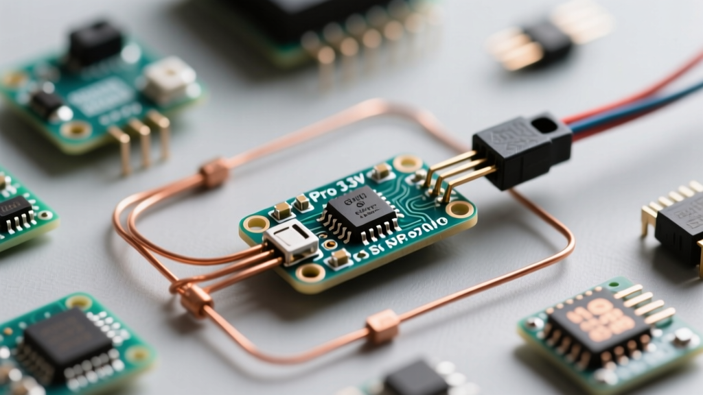

The Barebones Appeal of the Pro Mini
When you first unbox an Arduino Pro Mini 3.3 V, the most striking feature is what is missing. There is no bulky USB-B connector, no onboard voltage regulator meant for high-current draw, and often, no power LED. This stripped-down iteration of the classic Arduino platform is built around the ATmega328P microcontroller, but it is designed for one specific purpose: permanent, low-power, embedded installations.
For beginners transitioning from the plug-and-play simplicity of the Arduino Uno, the Pro Mini presents a unique hardware hurdle. Because it lacks an onboard USB-to-serial converter, you cannot simply plug it into your laptop to upload code. Instead, you must use an external FTDI adapter. This guide will walk you through the exact wiring, IDE configuration, and hardware quirks required to successfully program and deploy the 3.3V / 8MHz variant of this legendary board in 2026.
Why Choose the 3.3V / 8MHz Variant?
The Pro Mini historically comes in two flavors: a 5V version running at 16MHz, and a 3.3V version running at 8MHz. While the 5V board is faster and matches standard TTL logic, the 3.3V variant is the undisputed king of battery-operated IoT and sensor nodes.
| Feature | Pro Mini 5V (16MHz) | Pro Mini 3.3V (8MHz) |
|---|---|---|
| Logic Level | 5V | 3.3V |
| Clock Speed | 16 MHz | 8 MHz |
| Max RAW Input Voltage | 12V (Recommended) | 5V - 6V (Clone LDO Limit) |
| Battery Compatibility | Requires Buck Converter for Li-Ion | Direct Li-Ion (3.7V - 4.2V) Ready |
| Active Power Draw | ~15mA | ~5mA |
The 3.3V logic level natively matches modern sensors (like the BME280 or MPU6050) and wireless modules (like the NRF24L01 or LoRa transceivers) without requiring logic level shifters. Furthermore, the 8MHz clock speed allows the ATmega328P to operate safely at lower voltages, making it perfect for direct connection to a single-cell Lithium-Ion battery (which ranges from 4.2V fully charged down to 3.0V depleted).
The FTDI Hurdle: How to Actually Program It
To upload a sketch, you need a USB-to-Serial adapter. The most reliable options are based on the FT232RL or CP2102N chips. Ensure your adapter has a physical switch or jumper to select 3.3V logic output; feeding 5V serial data into the 3.3V Pro Mini's RX pin can permanently damage the microcontroller over time.
Step-by-Step FTDI Wiring
Follow this exact pinout to bridge your FTDI adapter to the Pro Mini's 6-pin serial header:
- GND to GND: Connect the ground pins to establish a common reference.
- VCC to VCC: Connect the 3.3V output of the FTDI to the VCC pin of the Pro Mini. Do not use the RAW pin for FTDI power.
- TX to RX: Connect the FTDI Transmit pin to the Pro Mini Receive pin (Pin 0).
- RX to TX: Connect the FTDI Receive pin to the Pro Mini Transmit pin (Pin 1).
- DTR to GRN: This is the most critical step for beginners. Connect the FTDI's DTR (Data Terminal Ready) pin to the Pro Mini's 'GRN' pin. This triggers the onboard 0.1µF capacitor, automatically resetting the board right before the bootloader expects incoming code.
Pro-Tip: If your specific FTDI adapter lacks a DTR pin but has an RTS pin, you can manually wire the RTS pin to the Pro Mini's 'RST' pin, but you will need to press the physical reset button on the Pro Mini exactly when the Arduino IDE says 'Uploading...' in the console.
IDE Configuration
In the Arduino IDE (version 2.x or later), navigate to Tools > Board > Arduino AVR Boards and select Arduino Pro or Pro Mini. Next, go to Tools > Processor and strictly select ATmega328P (3.3V, 8MHz). Selecting the 5V/16MHz option will cause your timing functions (like delay() and millis()) to run at exactly half-speed due to the clock mismatch.
Common Beginner Mistakes and Hardware Failure Modes
Because the Pro Mini is a barebones board, it lacks the protective circuitry found on the Uno. Avoid these common pitfalls:
- Overvoltage on the RAW Pin: The 3.3V clones typically use an ME6211C33 or MIC5205 low-dropout (LDO) regulator. While the 5V board can accept up to 12V on the RAW pin, feeding more than 6V into the RAW pin of a 3.3V clone will cause the LDO to overheat and enter thermal shutdown, or worse, fail short and send raw voltage straight to the 3.3V ATmega328P, instantly bricking it.
- Insufficient Current for Radios: The onboard LDO is usually rated for a maximum of 150mA. If you are driving an RFM95 LoRa module (which can spike to 120mA during transmission) alongside sensors, you will experience brownouts. Bypass the onboard LDO by powering the board via the VCC pin directly from a dedicated 3.3V buck converter.
- Ignoring the I2C Pull-ups: The Pro Mini does not have onboard I2C pull-up resistors. When wiring SDA and SCL lines to sensors, you must add external 4.7kΩ pull-up resistors to the 3.3V rail, or the
Wirelibrary will hang indefinitely.
Mastering Low-Power Sleep Modes
The primary reason engineers choose the Arduino Pro Mini 3.3 V in 2026 is its ability to sip microamps of current during sleep. According to the Microchip ATmega328P Datasheet, the chip can draw as little as 0.1µA in power-down mode.
However, the board's supporting components will ruin this efficiency if left intact. To achieve true ultra-low power, you must perform two hardware modifications:
- Remove the Power LED: Use a hot air gun or soldering iron to desolder the power LED resistor (usually marked 'R1' or 'R2'). This saves roughly 1.5mA to 3mA of continuous draw.
- Remove the Voltage Regulator: If you are powering the board directly from a 3.0V to 3.3V source (like a CR2032 coin cell or a regulated buck converter), desolder the 3-pin LDO on the edge of the board. The LDO's quiescent current draws an additional 50µA to 80µA even when the MCU is asleep.
For the software side, avoid the standard delay() function. Instead, utilize the watchdog timer or external interrupts. The legendary Nick Gammon's AVR Power Saving Guide details how disabling the ADC (Analog-to-Digital Converter) and BOD (Brown-Out Detector) before sleep is mandatory. Using the widely adopted LowPower library, your sleep call should look like this:
LowPower.powerDown(SLEEP_FOREVER, ADC_OFF, BOD_OFF);
This single line drops the board's current consumption from ~5mA down to roughly 0.12µA, allowing a standard 2000mAh 18650 Lithium-Ion cell to power the board in standby for over 1,500 years (theoretically, discounting battery self-discharge).
Sourcing in 2026: Clones vs. Modern Alternatives
SparkFun originally designed the Pro Mini, but they officially retired the board years ago to focus on modern ARM-based alternatives. Today, the market is flooded with overseas clones. These clones are incredibly cheap (often $3 to $5 per unit in bulk) and generally reliable, though quality control on the soldering of the 8MHz ceramic resonator can occasionally be poor.
If you are starting a new commercial product or require native USB without an FTDI adapter, consider the SparkFun RedBoard Artemis Nano or the Adafruit Feather 328P. These boards offer the same 3.3V ATmega328P architecture but include integrated Li-Po charging circuits and native USB-C or Micro-USB connectivity. However, for sheer cost-effectiveness and minimal footprint in DIY weather stations, soil moisture monitors, and hidden IoT nodes, the classic cloned Arduino Pro Mini 3.3 V remains entirely unbeatable.
Frequently Asked Questions
Can I power the 3.3V Pro Mini with a 9V battery?
No. While the 5V version handles 9V via the RAW pin, the 3.3V LDO regulator will overheat and fail when dropping 9V down to 3.3V. Limit RAW pin input to 5V maximum, or use a switching buck converter to step the 9V down to 3.3V before feeding it into the VCC pin.
Why is my upload failing with 'Programmer is not responding'?
This is almost always caused by a missing or broken DTR connection. Without the DTR signal, the board does not automatically reset into the bootloader. Ensure your FTDI adapter is wired to the GRN pin, or manually press the reset button on the Pro Mini the exact moment the IDE finishes compiling and begins uploading.