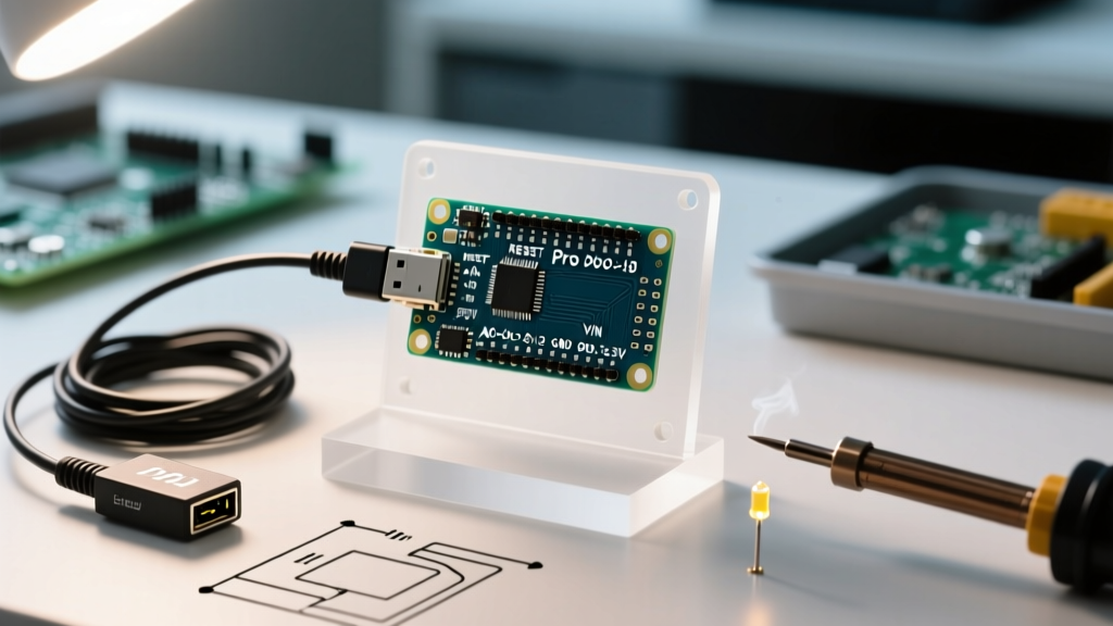

The Core Challenge: Stripped Down for Efficiency
Transitioning from the bulky Arduino Uno to the Arduino Pro Mini is a rite of passage for makers moving from breadboard prototypes to permanent, low-power installations. By stripping away the onboard USB-to-Serial converter and the power LED, the Pro Mini reduces quiescent current draw from roughly 45mA down to under 5mA. However, this minimalism introduces immediate hurdles for beginners: programming requires an external adapter, and the Arduino Pro Mini pinout features unique hardware quirks that differ significantly from standard UNO R3 boards.
In this guide, we will decode the exact pinout, walk through the mandatory FTDI programmer setup, and build a first project that specifically leverages the board's hidden analog-only pins.
Complete Arduino Pro Mini Pinout Matrix
Unlike the Uno, the Pro Mini breaks out several pins that require careful handling. Below is the definitive mapping for the standard ATmega328P-based Pro Mini.
| Silkscreen Label | ATmega328P Pin | Primary Function | Pro Mini Specific Quirk / Warning |
|---|---|---|---|
| RAW | N/A (Regulator In) | Unregulated Voltage Input | Feeds the onboard MIC5205 LDO. Requires at least 0.35V above VCC to regulate properly. |
| GND | GND | System Ground | Multiple GND pins are tied together. Use the one nearest to your power source to reduce ground loops. |
| RST | PC6 / Reset | Active Low Reset | Pulled high via 10kΩ resistor. Must be pulsed low to enter the bootloader. |
| VCC | VCC | Regulated 5V or 3.3V | Determined by the board variant. Never apply more than 5.5V here, or you will bypass the regulator and fry the MCU. |
| A6 / A7 | ADC6 / ADC7 | Analog Input Only | Critical: These are hardwired to the ADC multiplexer. They cannot be used as digital I/O and lack internal pull-up resistors. |
| GRN / BLK | N/A (FTDI Header) | DTR / Ground | Used for auto-reset during programming. GRN connects to DTR via a 0.1µF capacitor. |
Mandatory Setup: Wiring the USB-to-Serial Programmer
Because the Pro Mini lacks an onboard USB interface, you must use a USB-to-Serial adapter (commonly an FT232RL or CP2102 module) to upload code. In 2026, generic FT232RL adapters cost around $3.50, while official FTDI cables run closer to $22.00.
The Voltage Matching Trap
Pro Minis are sold in two distinct variants: 5V/16MHz and 3.3V/8MHz. You must match your FTDI adapter's logic level to the Pro Mini's VCC. If you attempt to program a 3.3V Pro Mini using a 5V FTDI adapter, the 5V logic signals on the RX/TX pins will exceed the ATmega328P's absolute maximum ratings, potentially degrading or destroying the silicon over time.
Solving the DTR Auto-Reset Issue
The 6-pin FTDI header on the Pro Mini features a pin labeled GRN (Green). This corresponds to the Data Terminal Ready (DTR) signal. When the Arduino IDE initiates an upload, it pulses DTR low, which passes through an onboard 0.1µF capacitor to momentarily pull the RST pin low, triggering the bootloader.
Troubleshooting Edge Case: If you are using a budget CP2102 breakout board that does not expose a DTR pin, your code will compile but fail to upload with an "avrdude: stk500_getsync() attempt 10 of 10" error. To fix this without buying a new adapter, you must manually press and release the Pro Mini's tiny reset button at the exact moment the IDE status bar changes to "Uploading...".
First Project: Analog-Only Soil Moisture Monitor
For our first project, we will intentionally use the A6 pin. Many makers incorrectly assume A6 and A7 function exactly like A0 through A5. According to the Microchip ATmega328P Datasheet, ADC6 and ADC7 are exclusively connected to the analog multiplexer and do not have corresponding digital data direction registers (DDRC). This makes them perfect for dedicated, permanent analog sensors where you want to save digital pins for I2C or SPI communications.
Hardware Bill of Materials (2026 Pricing)
- Arduino Pro Mini (3.3V/8MHz) - $3.20 (Generic Clone)
- Capacitive Soil Moisture Sensor v1.2 - $1.80 (Avoid resistive sensors, they corrode within days)
- FT232RL USB-to-Serial Adapter - $3.50
- 18650 Lithium-Ion Battery & Holder - $4.00
Wiring Guide
- Connect the Sensor
VCCto the Pro MiniVCC. - Connect the Sensor
GNDto the Pro MiniGND. - Connect the Sensor
AOUT(Analog Out) directly to the Pro MiniA6pin. - Wire the FTDI adapter:
GNDtoBLK,VCCtoVCC,TXtoRX,RXtoTX, andDTRtoGRN.
Calibration Code
Upload the following sketch to establish your wet/dry baseline. Because A6 lacks an internal pull-up resistor, we rely entirely on the sensor's output voltage divider.
const int sensorPin = A6; // Analog-only pin
int airValue = 0;
int waterValue = 0;

void setup() {
  Serial.begin(9600); // Use 9600 for 8MHz 3.3V boards
  Serial.println("Calibrating... Keep sensor in AIR.");
  delay(2000);
  airValue = analogRead(sensorPin);
  Serial.println("Now submerge sensor in WATER.");
  delay(3000);
  waterValue = analogRead(sensorPin);
  Serial.print("Air: "); Serial.print(airValue);
  Serial.print(" | Water: "); Serial.println(waterValue);
}

void loop() {
  int currentRead = analogRead(sensorPin);
  int moisturePercent = map(currentRead, airValue, waterValue, 0, 100);
  moisturePercent = constrain(moisturePercent, 0, 100);
  Serial.print("Moisture: "); Serial.print(moisturePercent); Serial.println("%");
  delay(1000);
}
Note: For a deeper understanding of how the ADC multiplexer handles analogRead() timing, refer to the official Arduino analogRead reference.
Advanced Power Routing: RAW vs. VCC
A frequent failure mode in permanent Pro Mini deployments involves misunderstanding the onboard voltage regulator. The board typically uses a MIC5205 Low Dropout (LDO) regulator. The "dropout voltage" is roughly 350mV.
If you are using a 5V Pro Mini and you feed exactly 5.0V into the RAW pin, the LDO cannot maintain a 5.0V output. The VCC pin will droop to approximately 4.65V. While the ATmega328P can run at 4.65V, operating a 16MHz crystal oscillator below the recommended 4.5V threshold can cause timing drift and serial communication baud-rate mismatches.
The Ultra-Low Power Bypass
If you are building a battery-powered node using sleep modes, the onboard LDO and the power LED (if not physically removed) will drain your battery. For true low-power operation (achieving micro-amp sleep currents), you must bypass the RAW pin entirely. Instead, feed a regulated 3.3V directly into the VCC pin, completely skipping the inefficient onboard LDO. This is the preferred method for LoRaWAN and ESP-NOW sensor nodes in 2026.
Summary
Mastering the Arduino Pro Mini pinout requires acknowledging what has been removed as much as understanding what remains. By properly matching your FTDI logic levels, leveraging the analog-only A6/A7 pins for dedicated sensors, and respecting the LDO dropout voltage on the RAW pin, you transform this $3 clone board into a highly reliable, professional-grade embedded controller.