
The 2026 Landscape: Evaluating the Arduino Uno Pinout for Modern Projects
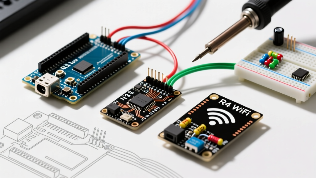
When evaluating the pinout Arduino Uno for embedded system design, engineers and makers must look beyond the basic silkscreen labels printed on the PCB. In 2026, the Arduino ecosystem is split between the legacy ATmega328P-based Uno R3 and the modern Renesas RA4M1-based Uno R4 Minima. While the physical footprint and header arrangements remain identical to preserve shield compatibility, the underlying electrical characteristics of the pinout have diverged significantly. Understanding these nuances is critical for project suitability analysis, ensuring you do not exceed current limits, misallocate communication buses, or destroy sensitive peripherals.
This guide provides a deep-dive technical analysis of the Arduino Uno pinout, mapping specific I/O capabilities to real-world project requirements, from precision sensor interfacing to high-speed motor control.
Power Rail Suitability: Sourcing vs. Sinking Constraints
The power pins on the Uno dictate the viability of your entire sensor network. The standard pinout exposes 5V, 3.3V, VIN, and multiple GND pins. However, the current sourcing capabilities differ drastically between board revisions.
The 5V Rail and USB Polyfuse Limitations
On the classic Uno R3, the 5V pin is tied to the USB 5V line (when powered via USB) through a 500mA resettable polyfuse. If you are designing a project with multiple 5V sensors (e.g., three HC-SR04 ultrasonic sensors and an I2C OLED display), you must calculate the cumulative current draw. The onboard NCP1117 5V linear regulator (used when powering via the barrel jack or VIN pin) can safely dissipate only about 800mA before thermal shutdown, and realistically, you should limit VIN-sourced 5V current to 400mA to avoid overheating the board.
The Uno R4 Minima utilizes a more efficient power architecture, but the 5V pin is still limited by the USB-C power delivery negotiation and onboard routing. For projects requiring >500mA at 5V (such as driving high-torque servos or NeoPixel LED matrices), the Uno pinout is unsuitable for direct power delivery. You must route external power directly to the load, using the Uno's 5V pin only for logic-level references.
The 3.3V Rail: A Hidden Bottleneck
Many modern sensors (e.g., BME280, MPU6050) require 3.3V logic. On the Uno R3, the 3.3V pin is generated by an onboard LDO that is strictly limited to 50mA. Attempting to power a Wi-Fi module or a high-draw 3.3V sensor array directly from the R3's 3.3V pinout will cause voltage sag and brownouts. The R4 Minima improves this, but best practice for 2026 project design dictates using a dedicated external 3.3V LDO (like the AMS1117-3.3) if your 3.3V load exceeds 30mA.
Expert Insight: Never back-feed power into the 5V pin while the USB cable is connected. The Uno R3 lacks an active hardware protection diode to prevent 5V from fighting your USB host's power supply, which can permanently damage your computer's USB controller or the board's ATmega16U2 USB-to-Serial IC.
Digital I/O, PWM, and Interrupt Mapping
The digital pinout (Pins 0-13) is the workhorse of any Uno project. However, not all digital pins are created equal. Suitability for specific tasks depends on hardware timers, interrupt vectors, and PWM resolution.
PWM Suitability for Motor and Audio Control
The Uno R3 features 6 PWM pins (3, 5, 6, 9, 10, 11) driven by three 8-bit hardware timers, outputting a fixed frequency of ~490 Hz (or ~980 Hz on pins 5 and 6). This is suitable for basic DC motor speed control via MOSFETs but entirely unsuitable for audio generation or high-frequency switching power supplies due to audible noise and switching losses.
The Uno R4 Minima drastically changes this suitability profile. It offers 12-bit DAC output on pin A0 and hardware PWM on almost all digital pins with much higher frequency flexibility, making it highly suitable for basic waveform generation and precision LED dimming without the flicker issues inherent to the R3.
External Interrupts and Real-Time Event Capture
For projects requiring microsecond-accurate event capture (e.g., flow meters, rotary encoders, or anemometers), you must use hardware interrupts. On the Uno R3, only Pins 2 and 3 support external interrupts (INT0 and INT1). If your project requires three or more independent interrupt-driven sensors, the Uno R3 pinout is fundamentally unsuitable, and you should migrate to a Mega2560 or implement complex Pin Change Interrupt (PCINT) software routines, which introduce jitter. The R4 Minima expands interrupt capability to almost all digital pins, vastly improving its suitability for complex event-driven architectures.
Comparison Matrix: Uno R3 vs. Uno R4 Minima Pinout Features
| Feature / Pinout Aspect | Uno R3 (ATmega328P) | Uno R4 Minima (Renesas RA4M1) |
|---|---|---|
| MCU Architecture | 8-bit AVR @ 16 MHz | 32-bit ARM Cortex-M4 @ 48 MHz |
| Operating Voltage | 5V Logic | 5V Logic (3.3V tolerant I/O) |
| Digital I/O Pins | 14 (Pins 0-13) | 14 (Pins 0-13) |
| PWM Capable Pins | 6 (Pins 3, 5, 6, 9, 10, 11) | 11 (Almost all digital pins) |
| Analog Input Pins | 6 (A0-A5, 10-bit ADC) | 6 (A0-A5, 14-bit ADC) |
| DAC Output | None | 1 (12-bit DAC on A0) |
| Hardware UART | 1 (Pins 0, 1) | 1 (Pins 0, 1) |
| I2C / SPI Buses | 1 / 1 | 2 / 2 (Multiplexed on pinout) |
| Typical 2026 Pricing | $12 - $15 (Clones) | $27.50 (Genuine) |
Data sourced from Arduino Uno Rev3 Official Docs and Arduino Uno R4 Minima Official Docs.
Analog Inputs and ADC Precision Suitability
The analog pinout (A0 through A5) is frequently misunderstood. On the R3, these pins route to the ATmega328P's internal 10-bit Successive Approximation Register (SAR) ADC. This yields 1024 discrete steps over a 5V reference, resulting in a resolution of approximately 4.88mV per step.
Sensor Suitability Analysis
- Potentiometers & Joysticks: Highly suitable. The 10-bit resolution is more than adequate for human-input devices where mechanical noise exceeds the ADC's least significant bit (LSB) variance.
- Thermistors (NTC 10k): Marginally suitable. For a 0°C to 100°C range, 10-bit resolution yields roughly 0.1°C per step, but non-linear voltage division requires software oversampling to achieve stable 0.5°C accuracy.
- Load Cells & Strain Gauges: Unsuitable. The 4.88mV step size and inherent AVR ADC noise floor make the Uno R3 pinout incapable of reading the microvolt-level changes from a Wheatstone bridge without an external 24-bit ADC (like the HX711).
The Uno R4 Minima upgrades the analog pinout with a 14-bit ADC, dropping the resolution to ~0.3mV per step, vastly improving suitability for precision environmental monitoring and basic biomedical sensing (like EMG or ECG front-ends) directly from the analog headers.
Communication Protocols and Bus Capacitance
The physical pinout maps specific communication protocols to fixed hardware peripherals. Misallocating these pins is a primary cause of project failure.
I2C Bus Constraints (Pins A4/A5)
Pins A4 (SDA) and A5 (SCL) are hardcoded to the primary I2C bus on the R3. The ATmega328P I2C specification limits bus capacitance to 400pF. In practical terms, this means you can reliably connect about three to four standard I2C sensors using standard 20cm jumper wires. If your project requires long cable runs (>50cm) or more than five I2C devices, the standard pinout is unsuitable without adding I2C bus extender ICs (like the P82B715) or active 4.7kΩ pull-up resistors to overcome line capacitance.
SPI and UART Conflicts
SPI is mapped to Pins 11 (MOSI), 12 (MISO), and 13 (SCK). A common edge case occurs when developers attempt to use Pin 13 for a standard digital output (like a status LED) while simultaneously running an SPI SD card module. The SPI clock signal will cause the LED to flicker erratically, and the added capacitance of the LED circuit can corrupt high-speed SPI data transfers. Furthermore, Pins 0 (RX) and 1 (TX) are shared with the USB-to-Serial chip. Connecting external 5V UART devices directly to these pins while the USB is plugged in will cause bus contention, potentially damaging the ATmega328P or the USB interface IC.
Critical Failure Modes and Edge Cases to Avoid
To ensure long-term project reliability, avoid these common pinout misapplications:
- Direct Inductive Load Switching: Never connect a relay coil or solenoid directly to a digital I/O pin. The inductive kickback will exceed the 40mA absolute maximum rating and the 5V clamp diode limits, instantly destroying the microcontroller port. Always use a 2N2222 BJT or logic-level MOSFET with a 1N4148 flyback diode.
- Exceeding the VCC/GND Aggregate Limit: While a single pin can source 20mA continuously (40mA absolute max), the ATmega328P has a total package current limit of 200mA across all VCC and GND pins combined. Powering eight LEDs at 20mA each (160mA total) leaves almost no headroom for the MCU's own logic operations, leading to brownouts.
- Hot-Swapping Shields: The Uno pinout does not feature hot-swap protection or sequenced power routing. Inserting or removing shields while the board is powered can cause momentary short circuits between the 5V and GND headers, or latch-up conditions in the CMOS silicon due to floating inputs.
Final Verdict on Project Suitability
The Arduino Uno pinout remains the gold standard for rapid prototyping, educational environments, and low-to-medium complexity IoT nodes. For projects requiring basic digital logic, simple PWM motor control, and standard I2C/SPI sensor integration, the Uno R3 (or its modern clones) is highly suitable and cost-effective. However, for 2026 projects demanding high-precision analog acquisition, complex interrupt handling, or native DAC outputs, the legacy R3 pinout falls short. In these scenarios, upgrading to the Uno R4 Minima preserves the physical shield compatibility while providing the 32-bit ARM architecture necessary for advanced embedded workloads.