
Decoding the Arduino Uno Supply Voltage Architecture
When engineers and makers evaluate the Arduino Uno supply voltage for a new embedded project, the conversation often stops at "it needs 5V." While the ATmega328P microcontroller at the heart of the classic Uno Rev3 operates at a nominal 5V, the board's actual power delivery network (PDN) is a complex web of linear regulators, polyfuses, and protection diodes. Understanding these hardware constraints is the difference between a prototype that works on a desk and a deployed node that survives in the field.
In this project suitability analysis, we break down the exact thermal and electrical limits of the Uno's power pathways, helping you decide if the classic Uno is viable for your specific application—or if you need to pivot to a switching regulator architecture or a different microcontroller platform entirely.
The Four Power Pathways: Capabilities and Risks
The Arduino Uno Rev3 offers four distinct methods for introducing power to the system. Each pathway interacts differently with the board's protection circuitry and voltage regulation stages.
1. USB Port (5V Nominal)
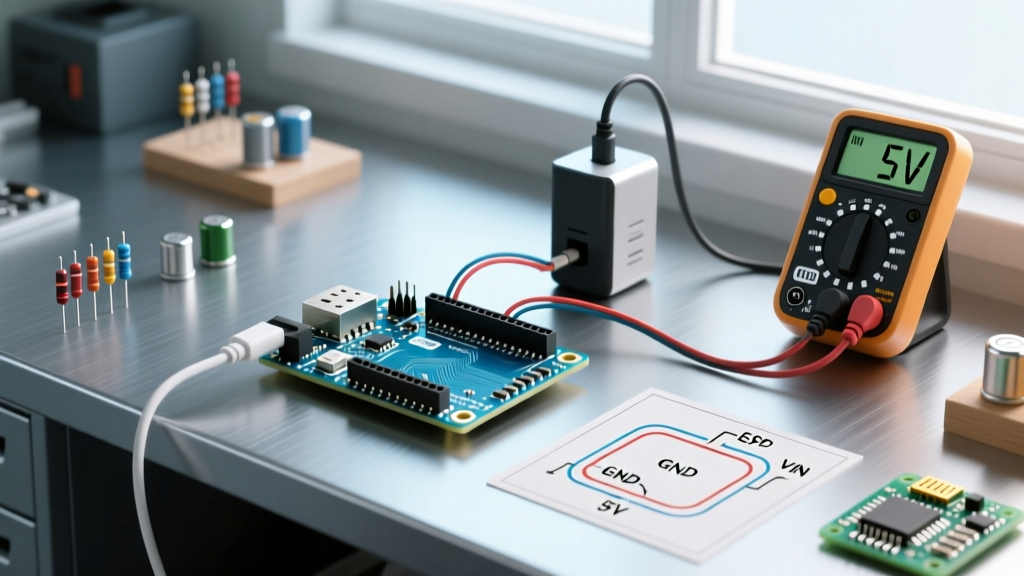
Powering the Uno via the USB-B connector bypasses the onboard linear regulator entirely. The 5V from your PC or wall adapter is routed through a resettable PTC polyfuse (rated at 500mA) directly to the 5V rail. This is the safest method for low-power desktop prototyping, but the 500mA hard ceiling limits its suitability for driving high-current peripherals like multiple servos or solenoid valves.
2. DC Barrel Jack (7V–12V Recommended)
The barrel jack feeds into the board's primary voltage regulator. While the official Arduino hardware documentation lists the absolute maximum input as 20V, operating anywhere near this limit will trigger catastrophic thermal shutdown. The recommended sweet spot is 7V to 12V, which balances regulator dropout voltage with thermal dissipation.
3. VIN Pin (Raw Input)
Electrically identical to the barrel jack, the VIN pin is preferred for custom PCB shields and permanent installations because it eliminates the mechanical failure points of a DC jack. It feeds directly into the same linear regulator circuit.
4. The 5V Pin (The Danger Zone)
⚠️ Critical Warning: Injecting 5V directly into the "5V" header pin completely bypasses the board's reverse polarity protection diode and the USB polyfuse. If your external 5V source experiences a voltage spike or is wired with reversed polarity, you will instantly destroy the ATmega328P and the USB-to-Serial ATmega16U2 chip.
The Linear Regulator Bottleneck: Thermal Math
The most critical limiting factor in the Arduino Uno supply voltage equation is the onboard NCP1117ST50T3G linear drop-out (LDO) regulator. Linear regulators operate by burning off excess voltage as heat. As SparkFun's voltage regulator guide explains, the power dissipated by an LDO is calculated as: P = (V_in - V_out) × I_load.
The NCP1117 in a SOT-223 package has a junction-to-ambient thermal resistance of roughly 50°C/W. If the ambient temperature is 25°C, and the regulator dissipates 1.5W, the junction temperature will spike to 100°C, nearing the 125°C thermal shutdown threshold. This physics limitation strictly dictates project suitability.
Thermal Limit Matrix: Input Voltage vs. Safe Current
| Input Voltage (VIN) | Voltage Drop | Max Safe Continuous Current | Thermal State (25°C Ambient) | Project Suitability |
|---|---|---|---|---|
| 6.5V | 1.5V | ~650mA | Warm (~75°C) | Excellent (Near dropout limit) |
| 9V | 4.0V | ~300mA | Hot (~85°C) | Good for sensor nodes |
| 12V | 7.0V | ~150mA | Very Hot (~105°C) | Poor (Risk of thermal throttling) |
| 15V+ | 10V+ | <50mA | Thermal Shutdown | Unusable without external buck |
Note: "Safe Current" refers to the total current drawn from the 5V rail, including the microcontroller, LEDs, and any shields.
Project Suitability Analysis by Use Case
Based on the power delivery constraints outlined above, here is how the classic Arduino Uno fares across common 2026 embedded project categories.
Scenario A: Remote IoT Environmental Sensor Node
- Power Source: 3x AA Alkaline Batteries (4.5V) or Li-Ion via USB.
- Suitability: Low. The Uno lacks native deep-sleep modes that drop current to the microamp range. Furthermore, running 4.5V into the 5V pin will cause brownouts because it is below the ATmega328P's stable 5V operating threshold at 16MHz. For battery-operated IoT, a 3.3V Arduino Pro Mini or an ESP32-C3 is vastly superior.
Scenario B: Desktop Robotics & Servo Control
- Power Source: 12V DC Wall Adapter via Barrel Jack.
- Suitability: Moderate to Poor. A standard SG90 micro servo draws ~200mA under stall conditions. Two servos connected to the Uno's 5V rail will pull 400mA. At 12V input, the LDO must dissipate
(12-5) * 0.4 = 2.8W. This will trigger immediate thermal shutdown. Solution: Use the 12V adapter to power a separate external buck converter (like an LM2596 module set to 5V) to drive the servos, tying only the grounds together.
Scenario C: Automotive Data Logging (OBD-II)
- Power Source: Vehicle 12V-14.4V system via VIN.
- Suitability: High (with caveats). Automotive environments are notorious for load dump transients that can spike to 40V. While the Uno's LDO might survive steady-state 14V if the current draw is kept under 100mA (e.g., reading CAN bus data via an MCP2515 shield), you must add an external TVS (Transient Voltage Suppression) diode and an LC filter on the VIN line to protect against alternator whine and inductive spikes.
Edge Cases and Common Failure Modes
When designing enclosures and wiring harnesses for Uno-based projects, keep these specific failure modes in mind:
- USB Backfeeding: If you power the Uno via the barrel jack while simultaneously connecting it to a PC via USB, the onboard voltage comparator (an LMV358 op-amp) switches a P-channel MOSFET to select the higher voltage source. If the MOSFET fails or is bypassed, 12V can backfeed into your PC's USB port, destroying the motherboard.
- Inductive Kickback Resets: Switching relays directly from the Uno's 5V rail without flyback diodes will inject reverse voltage spikes into the 5V plane, causing the ATmega328P to brownout and reset randomly.
- Capacitor Inrush: Adding large bulk capacitors (e.g., 1000µF) directly to the 5V pin can cause an inrush current that trips the USB polyfuse or damages the LDO upon initial power-up.
Modern Alternatives and Upgrades
If your project suitability analysis reveals that the classic Uno's linear power tree is a bottleneck, consider these modern alternatives:
- Arduino Uno R4 WiFi: Features a more robust power management IC and an integrated ESP32-S3, though it still relies on linear regulation for the primary 5V rail. It is better suited for IoT but still requires external switching regulators for high-current actuators.
- External DC-DC Buck Converters: For any project drawing more than 200mA from a 9V+ source, integrating a switching regulator like the Texas Instruments LM2596 is mandatory. Switching regulators achieve 85%+ efficiency, converting 12V to 5V with minimal heat generation compared to the LDO's 40% efficiency.
Final Verdict
The Arduino Uno supply voltage architecture is a masterpiece of educational simplicity but a limitation for professional deployment. It is perfectly suited for low-current, USB-powered desktop prototypes and sensor interfaces drawing under 150mA from the VIN pin. However, for motor control, high-brightness LED matrices, or battery-constrained wearables, the Uno's linear regulator and lack of native power-saving modes make it unsuitable. Always calculate your LDO thermal budget before finalizing your BOM, and never hesitate to offload high-current tasks to dedicated switching power supplies.