
The Tale of Two Documents: Board Schematic vs. MCU Datasheet
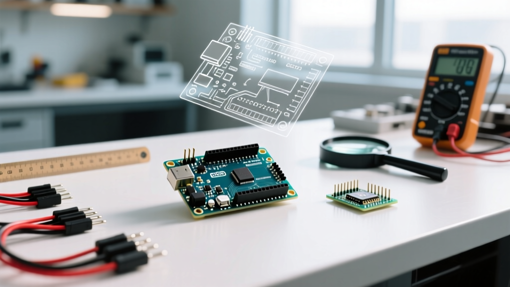
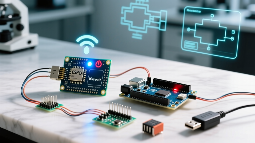
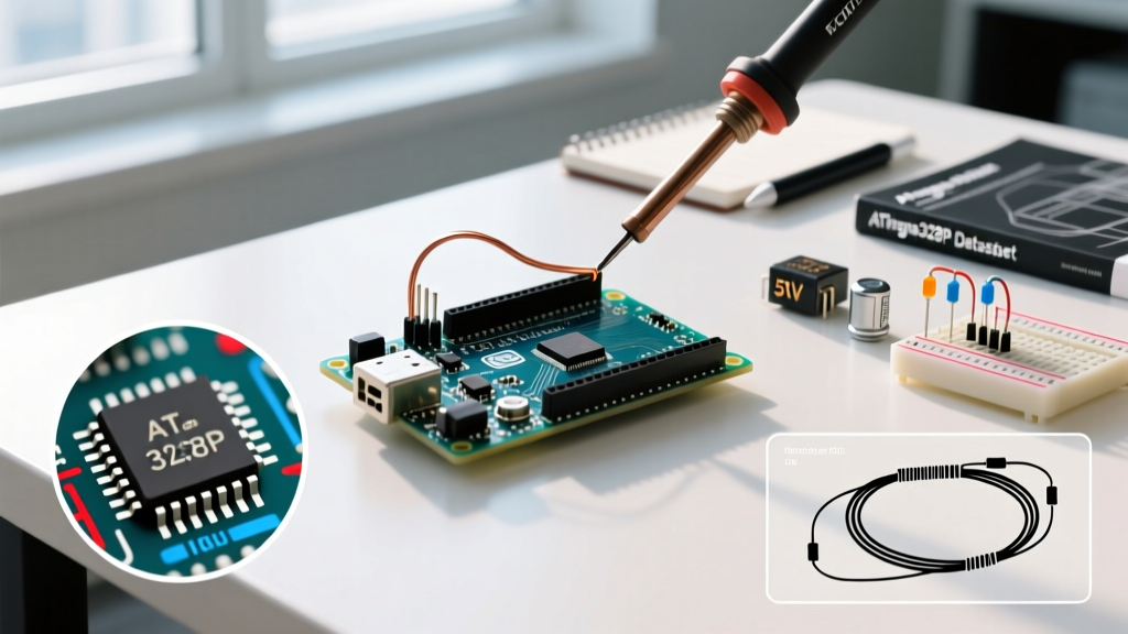
When beginners search for the arduino uno datasheet, they are usually met with two entirely different documents. The first is the Arduino Uno Rev3 Board Schematic, which details the supporting circuitry: the NCP1117 5V voltage regulator, the ATmega16U2 USB-to-Serial converter, and the Murata 16MHz ceramic resonator. The second—and far more critical for your code and hardware design—is the Microchip (formerly Atmel) ATmega328P Microcontroller Datasheet.
Understanding the distinction is the foundation of electrical DIY expertise. The board schematic tells you what components are physically soldered to the PCB, but the ATmega328P datasheet dictates the actual silicon limits, register maps, and timing diagrams of the brain itself. In 2026, while newer platforms like the Uno R4 Minima dominate high-performance markets, the classic ATmega328P-based Uno R3 remains the undisputed educational baseline. A genuine Uno R3 currently retails for around $28 to $32, while high-quality clones with CH340 USB chips hover around $14. Regardless of which you purchase, the silicon rules remain identical.
Extracting the ATmega328P Absolute Maximum Ratings
Fried microcontrollers rarely happen by accident; they happen when builders ignore the Microchip ATmega328P specifications. The datasheet explicitly separates "Absolute Maximum Ratings" from "Recommended Operating Conditions." Exceeding the absolute maximums even for a millisecond can cause permanent silicon degradation.
| Parameter | Absolute Maximum | Recommended Safe Limit | Engineering Notes |
|---|---|---|---|
| DC Current per I/O Pin | 40.0 mA | 20.0 mA | Running at 40mA causes excessive heat and electromigration over time. |
| Total VCC/GND Current | 200.0 mA | 150.0 mA | The sum of all current sourced/sunk across all ports combined. |
| Operating Voltage (VCC) | 6.0V | 4.5V - 5.5V | The board's 5V pin is regulated, but raw VCC on the chip must be stable. |
| Clock Frequency | 20 MHz | 16 MHz | Dictated by the onboard ceramic resonator, not the silicon's max capability. |
Expert Insight: The USB polyfuse on the Uno Rev3 (typically a Bourns MF-MSMF050-2) limits total USB current draw to 500mA. If your project draws 300mA via the 5V pin and the MCU draws 150mA across its I/O pins, you are dangerously close to tripping the host computer's USB overcurrent protection.
Step-by-Step Board Setup & IDE Configuration
Before wiring a single LED, your software environment must match the hardware's physical reality. As of 2026, the Arduino IDE 2.3.x is the standard. Follow these precise steps to ensure your compiler respects the 16MHz clock speed detailed in the datasheet:
- Install the Core: Open the Boards Manager and install the official
Arduino AVR Boardspackage (version 1.8.6 or newer). - Select the Target: Navigate to Tools > Board and select
Arduino Uno. Do not select 'ATmega328P on a breadboard' unless you are using an external crystal, as this changes the compiler's delay timing macros. - Verify the Port: Genuine boards use the ATmega16U2 and will show up as
/dev/ttyACM0(Linux) orCOM3(Windows). Clones using the CH340G chip require the specific CH340 driver and will appear asUSB-SERIAL CH340. - Programmer Selection: Ensure Tools > Programmer is set to
AVRISP mkIIfor standard USB uploads. You only need to change this if you are burning a fresh bootloader via ICSP headers using a tool like the USBasp.
First Project: Datasheet-Compliant PWM Breathing LED Array
Most "Blink" tutorials ignore current budgeting. For your first real project, we will build an 8-LED PWM breathing array that strictly adheres to the Arduino Uno Rev3 hardware limits. We will use pins 3, 5, 6, 9, 10, and 11 (the hardware PWM pins driven by Timer/Counter 1 and 2), plus pins 2 and 4 driven via software analog emulation if needed, but let's stick to the 6 true hardware PWM pins to respect the datasheet's timer architecture.
Wiring Diagram & Current Calculations
We are using standard 5mm Red LEDs with a forward voltage ($V_f$) of 2.1V and a target current ($I_f$) of 20mA. According to the datasheet, 20mA is the recommended continuous limit per pin.
- Ohm's Law Calculation: $R = (V_{source} - V_f) / I_f$
- Math: $R = (5.0V - 2.1V) / 0.020A = 145 \Omega$
- Component Selection: Use standard 150 Ohm (1/4W) carbon film resistors. This yields a safe 19.3mA per pin.
- Total Current Budget: 6 pins × 19.3mA = 115.8mA. This is well below the 150mA recommended total VCC limit and the 200mA absolute maximum.
Wire the anode (long leg) of each LED to the PWM pins through the 150 Ohm resistor, and tie all cathodes (short leg) to the board's common GND rail.
The C++ Code (With Datasheet Register Context)
While analogWrite() is convenient, understanding how it works via the ATmega328P datasheet's register map separates hobbyists from engineers. The Uno's pins 5 and 6 are controlled by Timer/Counter0 (8-bit), pins 9 and 10 by Timer/Counter1 (16-bit), and pins 3 and 11 by Timer/Counter2 (8-bit). Modifying Timer0 breaks the millis() function, so we will target Timer1 and Timer2 pins for our breathing effect.
// Datasheet-Optimized PWM Breathing Array (Pins 3, 9, 10, 11)
// Avoids Timer0 (Pins 5, 6) to preserve millis() and delay() accuracy

const int pwmPins[] = {3, 9, 10, 11};
const int numPins = 4;
int brightness = 0;
int fadeAmount = 2;

void setup() {
  for (int i = 0; i < numPins; i++) {
    pinMode(pwmPins[i], OUTPUT);
    // Under the hood, this configures the COM bits in the
    // TCCR1A and TCCR2A registers for non-inverting PWM mode.
  }
}

void loop() {
  for (int i = 0; i < numPins; i++) {
    analogWrite(pwmPins[i], brightness);
  }

  brightness = brightness + fadeAmount;

  if (brightness <= 0 || brightness >= 255) {
    fadeAmount = -fadeAmount;
  }

  // 30ms delay creates a smooth 7.6-second full breath cycle
  delay(30);
}
Edge Cases & Hardware Failure Modes
Even with perfect code and wiring, environmental factors can trigger hardware resets. The ATmega328P datasheet details a feature called Brown-out Detection (BOD). The Uno's factory-burned bootloader sets the BOD threshold to 2.7V. If you power the Uno via the barrel jack using a depleted 9V alkaline battery, the onboard NCP1117 regulator will drop out as the battery voltage sags under load. When the 5V rail dips below the BOD threshold, the MCU will instantly reset to prevent corrupted EEPROM writes or erratic logic states.
Troubleshooting the Auto-Reset Bug: Have you ever noticed your Uno resetting randomly when a relay switches off? This is often caused by inductive kickback inducing a voltage spike on the 5V rail, or a ground bounce that momentarily pulls the reset pin low. The Uno schematic includes a 0.1µF capacitor between the ATmega16U2 DTR line and the ATmega328P reset pin for auto-flashing. If you are building a permanent installation, you can disable this auto-reset feature by placing a 10µF electrolytic capacitor between the RESET and GND pins, absorbing transient spikes and stabilizing the line against EMI.
Final Takeaways for the DIY Engineer
Mastering the arduino uno datasheet is not about memorizing every page; it is about knowing where to look when a project fails. By respecting the 20mA per-pin limit, understanding the timer register allocations for PWM, and accounting for Brown-out Detection in your power supply design, you transition from simply copying tutorials to engineering robust, reliable electronic systems. For deeper architectural insights, consult the official Arduino microcontroller learning hub and keep the Microchip ATmega328P PDF bookmarked in your browser.