
Engineering with the Arduino Nano: Physical and Electrical Measurements
When integrating a microcontroller into a custom PCB, CNC-milled enclosure, or 3D-printed housing, relying on assumed dimensions leads to costly manufacturing errors. The Arduino Nano remains one of the most popular development boards for compact embedded systems, but its physical footprint and electrical tolerances require precise documentation. This guide provides exact arduino nano measurements, covering physical dimensions, pinout spacing, electrical limits, and a 2026 market comparison between official units and modern third-party clones.
Physical Arduino Nano Measurements (The Blueprint)
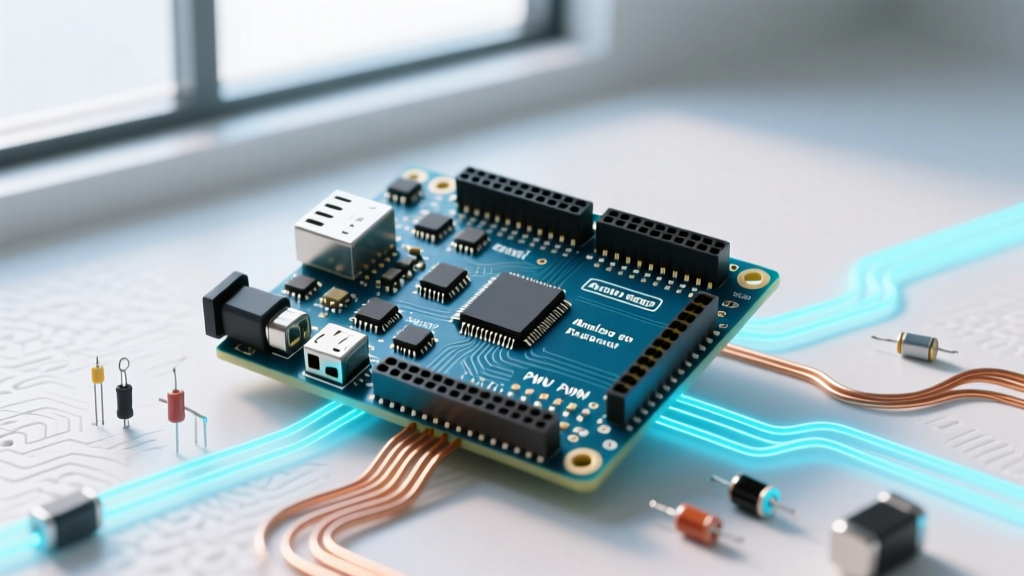
The classic Arduino Nano is designed to fit directly into a standard solderless breadboard, which dictates its core physical geometry. According to the official Arduino Nano documentation, the PCB dimensions are strictly standardized, though component overhangs require additional clearance.
- PCB Length: 45.0 mm (1.77 inches)
- PCB Width: 18.0 mm (0.71 inches)
- PCB Thickness: 1.6 mm (standard FR4)
- Total Height (Without Headers): ~7.0 mm (measured from PCB bottom to the top of the tallest SMD component, typically the crystal oscillator or USB port housing)
- Total Height (With Standard Male Headers): ~14.5 mm
- Weight: ~5.0 grams (without headers)
Critical Clearance Warning: The Mini-USB port on the official board extends past the edge of the PCB by approximately 2.5 mm. When designing a 3D-printed enclosure or a carrier board cutout, you must allocate at least 50.0 mm of total length clearance to accommodate the port overhang and cable strain relief.
The Mounting Hole Dilemma
Unlike the Arduino Uno or Mega, the classic Nano does not feature standard M2 or M3 mounting holes. This is a frequent trap for junior engineers designing carrier boards. To secure a Nano in a custom enclosure, you must either rely on friction-fit slots (requiring precise 0.2 mm manufacturing tolerances) or design custom spring-clip mechanisms. For permanent installations, direct soldering of the castellated edge pads or using low-profile SMD header sockets is the industry standard.
Pinout Spacing & Breadboard Compatibility
The Nano’s pinout is engineered specifically for standard 830-point and 400-point solderless breadboards. Understanding the exact spatial relationships between the header rows is vital for custom shield design.
| Measurement Parameter | Metric (mm) | Imperial (inches) | Engineering Notes |
|---|---|---|---|
| Header Pitch (Pin-to-Pin) | 2.54 mm | 0.100" | Standard 0.1" spacing across all 30 pins. |
| Row-to-Row Spacing (Center-to-Center) | 15.24 mm | 0.600" | Spans exactly 6 breadboard rows, leaving 1 row exposed on each side for wiring. |
| Header Pin Width (Square Post) | 0.64 mm | 0.025" | Standard male header post thickness. |
| Distance from Edge to Pin Row | 1.38 mm | 0.054" | Leaves minimal PCB trace routing space on the outer edges. |
Electrical Measurements & Power Specifications
Physical dimensions are only half the equation; electrical measurements dictate how the Nano interfaces with sensors, motors, and external power supplies. The classic Nano is built around the Microchip ATmega328P microcontroller, operating at 5V logic with a 16 MHz crystal oscillator.
Voltage and Current Limits
- Logic Level: 5.0V (TTL compatible). Applying 3.3V logic to RX/TX pins without a level shifter will result in unreliable serial communication.
- Recommended Input Voltage (VIN): 7V to 12V. The onboard linear voltage regulator (typically an AMS1117-5.0 on clones or similar LDO on official boards) will overheat and trigger thermal shutdown if input voltage exceeds 12V while drawing significant current.
- DC Current per I/O Pin: 20 mA is the absolute maximum rating. However, for long-term reliability and to prevent internal trace degradation, limit continuous draw to 15 mA per pin.
- Total VCC/GND Current Limit: 200 mA aggregate across all I/O pins.
- 3.3V Regulator Output: Capable of sourcing up to 150 mA, though this is shared with the onboard USB-to-Serial converter.
Official vs. Clone: 2026 Dimensional Variations
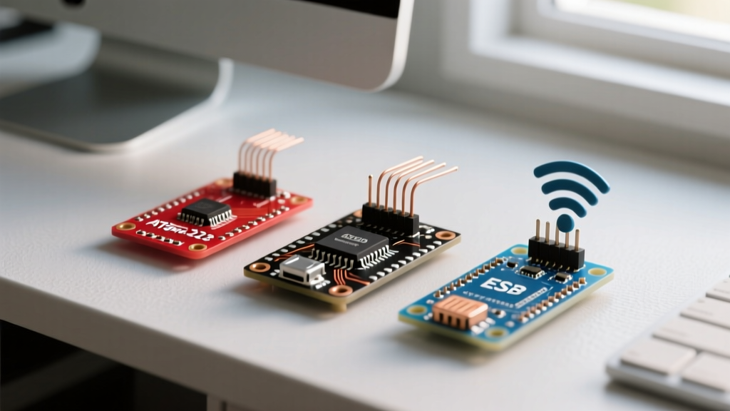
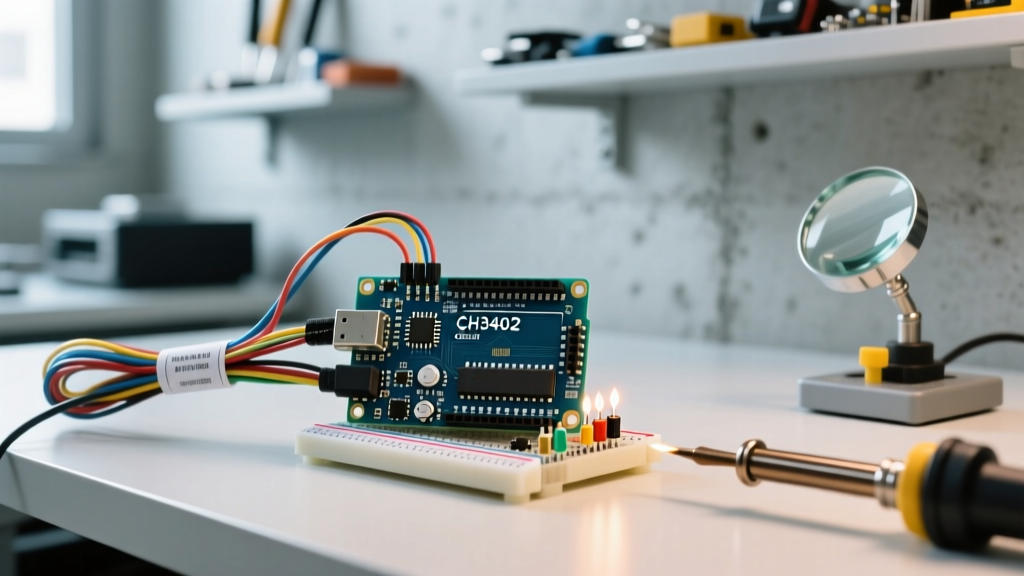
As of 2026, the market is saturated with third-party Nano clones. While they share the same core footprint, component substitutions alter the physical and electrical measurements in ways that affect mechanical design. You can review the baseline SKU on the official Arduino Store, but understanding clone deviations is critical for bulk manufacturing.
| Feature | Official Arduino Nano | Standard CH340 Clone (2026 USB-C) | Arduino Nano Every |
|---|---|---|---|
| PCB Dimensions | 18 x 45 mm | 18 x 45 mm (strict adherence) | 18 x 45 mm |
| USB Port Type | Mini-USB (Type-B) | USB-C (flush or 1mm overhang) | Micro-USB |
| USB-to-Serial IC | FTDI FT232RL | WCH CH340G or CH340C | Atmega4809 (Native USB) |
| Logic Voltage | 5.0V | 5.0V | 5.0V (with 3.3V I/O tolerance) |
| Typical Price (2026) | $24.50 - $27.00 | $3.50 - $5.00 | $11.00 - $13.00 |
| Bottom Component Clearance | ~2.5 mm | ~1.5 mm (CH340C is smaller) | ~2.0 mm |
Engineering Insight: If you are designing a carrier board where the Nano sits flush against another PCB, the older CH340G chip (a large SOIC-16 package) on early clones required a 3mm cutout in the bottom board. Modern 2026 clones utilizing the QFN-20 CH340C chip have a significantly lower bottom-profile, allowing for tighter vertical stacking tolerances.
Designing Enclosures and Custom PCBs
When translating these arduino nano measurements into CAD software (like Fusion 360, KiCad, or Altium), follow these actionable guidelines to prevent assembly failures:
- 3D Printing Tolerances: FDM 3D printers typically have a dimensional accuracy of ±0.2 mm. When designing a friction-fit slot for the Nano, model the slot at 18.4 mm wide and 48.0 mm long to account for the USB overhang and printer tolerances.
- KiCad Footprint Generation: Do not use generic 2x15 header footprints. Create a custom footprint with 2.54mm pitch and 15.24mm row spacing, but add a 50mm x 20mm courtyard outline on the F.Fab layer to represent the physical USB port overhang and prevent component collision.
- Thermal Management: If powering the Nano via the VIN pin at 12V, the onboard LDO will dissipate significant heat. Ensure your enclosure design includes ventilation slots directly above the voltage regulator (located on the bottom-left quadrant of the board) or apply a 5mm x 5mm adhesive copper heatsink.
Frequently Asked Questions (FAQ)
Does the Arduino Nano have mounting holes?
No. The classic Arduino Nano lacks dedicated mounting holes. Engineers must use friction-fit enclosures, custom 3D-printed clips, or solder the headers directly to a carrier board for mechanical stability.
What is the exact distance between the two rows of pins?
The center-to-center distance between the two 15-pin header rows is exactly 15.24 mm (0.6 inches). This specific measurement allows the board to straddle the center divider of a standard breadboard, leaving one row of holes accessible on either side.
How much does the USB port extend past the PCB edge?
On the official Mini-USB Nano, the port extends approximately 2.5 mm past the 45 mm PCB edge. Modern USB-C clones vary; some sit perfectly flush with the 45 mm edge, while others extend up to 1.5 mm. Always check the specific manufacturer's mechanical drawing before finalizing an enclosure mold.
Can I power the Nano with exactly 5V via the VIN pin?
No. The VIN pin feeds directly into the onboard voltage regulator's input. Supplying 5V to VIN will result in a voltage drop across the regulator, leaving the ATmega328P with roughly 3.5V to 4.0V, causing brownouts and unstable clock speeds. To power the Nano with 5V, bypass the regulator and inject power directly into the 5V pin, ensuring the USB cable is disconnected to prevent back-feeding and damaging your PC's USB port.