
The Synergy: Arduino Uno and Breadboard Prototyping in 2026
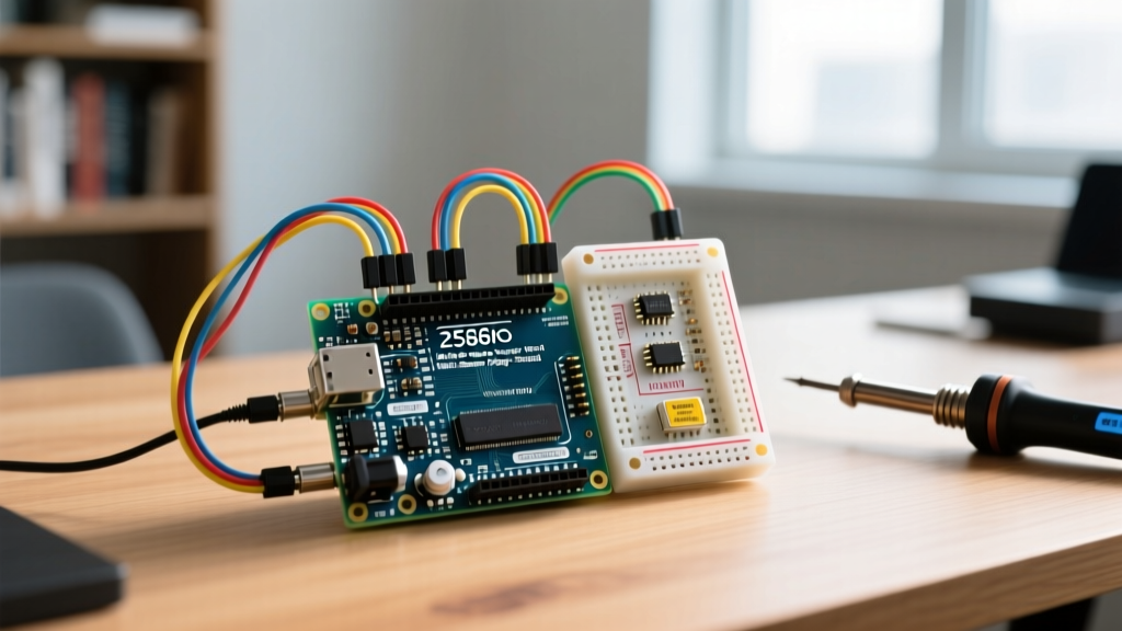
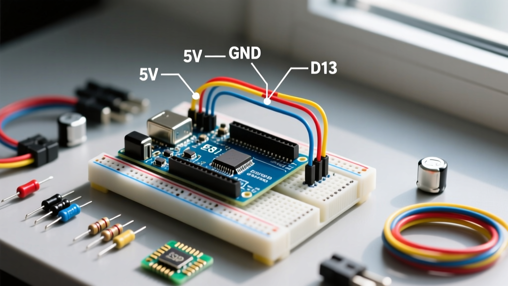
Even as the electronics landscape evolves with surface-mount dominance and integrated AI edge modules, the combination of the Arduino Uno and breadboard remains the undisputed foundation of rapid hardware prototyping. Whether you are deploying a legacy Arduino Uno R3 (typically retailing around $27) or the newer Uno R4 Minima ($20) and R4 WiFi ($27.50), the physical interface relies on the same 0.1-inch (2.54mm) pitch header standard. However, treating a solderless breadboard as a flawless conductor is a primary failure point for intermediate makers. This deep dive explores the electrical realities, mechanical limitations, and signal integrity pitfalls of pairing the Arduino Uno with a standard 830-point solderless breadboard.
Power Rail Architecture and Current Limits
The most catastrophic mistakes when wiring an Arduino Uno and breadboard occur on the power rails. Beginners often assume that because the board is powered by a USB cable capable of delivering 2A, the breadboard's red and blue rails have unlimited current access. This is fundamentally false.
CRITICAL WARNING: The Arduino Uno R3 features a resettable PTC polyfuse on the USB power line that trips at approximately 500mA. If your breadboarded sensors, LEDs, and actuators collectively draw more than 500mA from the 5V pin via USB, the polyfuse will trip, cutting power to the entire circuit until it cools down.
Furthermore, the 3.3V rail on the Uno R3 is heavily constrained. According to the official Arduino Uno R3 documentation, the 3.3V pin is derived from the onboard voltage regulator (or the USB-to-serial chip on certain revisions) and is strictly limited to a maximum of 50mA. Attempting to power a modern 3.3V Wi-Fi module or a high-brightness LED matrix from the R3's 3.3V breadboard rail will cause brownouts, erratic behavior, or permanent thermal damage to the regulator. The newer Uno R4 features a more robust power supply architecture, but respecting the physical limits of your specific board revision is non-negotiable.
Power Pin Limits Comparison Matrix
| Header Pin | Uno R3 Max Current | Uno R4 Minima Max Current | Breadboard Use Case & Notes |
|---|---|---|---|
| 5V | ~500mA (USB limited) | Up to 1.5A (via USB-C) | Main logic power; watch the R3 polyfuse limit. |
| 3.3V | 50mA (Strict Limit) | Up to 500mA | Low-power sensors only on R3; R4 handles more. |
| VIN | Depends on external PSU | Depends on external PSU | Use for 7-12V unregulated input from a barrel jack. |
| IOREF | Reference only | Reference only | Do not draw power; use only for logic level sensing. |
Step-by-Step Wiring Protocol for Reliable Connections
Signal integrity on a breadboard is entirely dependent on mechanical contact. The internal spring clips are designed for a specific wire gauge. Deviating from this specification causes intermittent connections that are notoriously difficult to debug with a multimeter.
- Select the Correct Wire Gauge: Always use 22 AWG (0.64mm) solid-core copper wire. Stranded wire will fray, jam the clips, and cause shorts. 24 AWG is too thin and will result in loose connections that vibrate open, while 20 AWG is too thick and will permanently stretch the breadboard's internal leaf springs, ruining the board for future 22 AWG use.
- Precision Stripping: Strip exactly 8mm (5/16 inch) of insulation from the wire ends. If you strip less (e.g., 5mm), the plastic insulation will bottom out against the breadboard housing before the copper makes contact with the internal clip, resulting in an open circuit. If you strip more (e.g., 12mm), you expose bare copper above the plastic surface, creating a severe short-circuit risk with adjacent 0.1-inch pitch rows.
- Insertion Angle: Insert the wire perfectly perpendicular to the breadboard face. Angled insertion can bend the internal metal clip backward, permanently destroying that specific node's connectivity.
- Routing Strategy: Keep high-current paths (like motor driver outputs) on the outer edges of the breadboard, and route sensitive analog signals (like ADC inputs) through the center, away from digital switching noise.
Hidden Failure Modes: Parasitics and Contact Resistance
When you wire an Arduino Uno and breadboard together, you are not just connecting copper; you are introducing parasitic electrical elements into your circuit. As detailed in comprehensive prototyping guides like SparkFun's breadboard tutorial, the physical layout of the breadboard inherently alters high-frequency signals.
The I2C and SPI Parasitic Capacitance Trap
Adjacent rows and columns on a standard solderless breadboard exhibit a parasitic capacitance of approximately 2pF to 5pF. While this is negligible for standard 9600-baud UART serial or basic GPIO toggling, it becomes a critical failure mode for high-speed buses.
- I2C Bus Glitches: If you run long jumper wires across the breadboard for an I2C OLED display or sensor, the added capacitance (often exceeding 100pF when combined with wire capacitance) softens the rising edges of the SDA and SCL lines. Solution: Always place 4.7kΩ pull-up resistors directly adjacent to the Arduino's A4/A5 pins on the breadboard, not near the sensor.
- SPI Signal Degradation: For SPI peripherals operating above 1MHz, the breadboard's parasitic capacitance can cause bit-shift errors. Solution: Keep SPI jumper wires (MOSI, MISO, SCK, CS) under 3 inches in length, and route them parallel to a ground wire to minimize loop inductance.
Contact Resistance and Voltage Drops
A fresh, high-quality breadboard has a contact resistance of about 10mΩ to 20mΩ per clip. However, as the board ages, or if exposed to high humidity, this resistance can climb to 100mΩ or more. If you are routing 500mA through a single breadboard jumper to power a servo motor, a 100mΩ contact resistance will drop 0.05V per connection point. Across a power rail, breadboard jumper, and ground return, you can easily lose 0.2V to 0.3V, causing microcontroller brownouts. Always use dual power jumpers (two wires for 5V, two for GND) for high-draw breadboarded modules.
Essential Decoupling and Signal Conditioning
Never trust the raw power rails of a breadboarded Arduino setup. Every active component you add to the breadboard (shift registers, op-amps, motor drivers) requires local decoupling.
Place a 100nF (0.1µF) ceramic capacitor as physically close as possible to the VCC and GND pins of every integrated circuit on your breadboard. The long, inductive paths of the breadboard's internal metal strips and jumper wires cannot supply the instantaneous microsecond current spikes required by digital logic switching. The 100nF capacitor acts as a localized, high-frequency energy reservoir, preventing voltage sag that would otherwise trigger the Arduino's internal brownout detection (BOD) and cause random resets.
Troubleshooting the Arduino Uno and Breadboard Matrix
When your circuit fails, use this targeted diagnostic checklist before rewriting your firmware:
- Floating Analog Inputs: If an unconnected analog pin (e.g., A0) reads random values between 0 and 1023, it is acting as an antenna. The high-impedance ADC input on the ATmega328P is susceptible to ambient electromagnetic interference. Always tie unused analog inputs to GND via a 10kΩ resistor on the breadboard.
- The 'Ghost' Reset: If your Arduino Uno resets every time you plug a high-current breadboarded component (like a relay module) into the 5V rail, you are experiencing a voltage sag. The ATmega328P requires a stable 5V. Use a separate, dedicated 5V buck converter on the breadboard powered by the Arduino's VIN pin for inductive loads.
- Intermittent Switch Bouncing: Mechanical pushbuttons wired to digital pins suffer from contact bounce. While the Arduino software digital pin architecture can handle debouncing in code, adding a hardware 100nF capacitor in parallel with the breadboarded switch provides a clean, hardware-level RC debounce filter.
Frequently Asked Questions (FAQ)
Can I use 24 AWG wire for my Arduino breadboard projects?
While 24 AWG solid core wire will physically fit into the breadboard holes, it is not recommended for permanent prototyping. The internal spring clips are optimized for 22 AWG. The thinner 24 AWG wire will not exert enough lateral pressure against the clips, leading to micro-vibrations breaking the circuit connection, especially if the breadboard is moved or bumped on your workbench.
Why is my I2C OLED display glitching when wired on the breadboard?
I2C glitches on a breadboard are almost always caused by weak pull-up resistors combined with parasitic capacitance. The Arduino Uno's internal pull-ups are roughly 30kΩ to 50kΩ, which is far too weak to pull the bus high quickly against the breadboard's capacitance. Add external 4.7kΩ or 3.3kΩ pull-up resistors to the 5V rail directly on the breadboard near the display's SDA and SCL pins.
How do I safely power high-draw servos from the breadboard?
Do not power servos directly from the Arduino Uno's 5V breadboard rail. A single standard SG90 servo can draw 700mA during stall, which will instantly trip the Arduino's USB polyfuse. Instead, use a dedicated 5V power supply module that plugs directly into the breadboard's power rails, and ensure you connect the ground of the external power supply to the Arduino's GND pin to maintain a common logic reference.