
Introduction to the Classic Nano Architecture
In the rapidly evolving landscape of 2026, where powerful boards like the Nano ESP32 and Raspberry Pi Pico 2 dominate advanced IoT projects, the classic ATmega328P-based Arduino Nano remains an undisputed staple for legacy prototyping, education, and custom PCB reference designs. Understanding the Arduino Nano schematic diagram is not just an academic exercise; it is a critical skill for hardware engineers designing custom carrier boards, troubleshooting field failures, and optimizing power consumption.
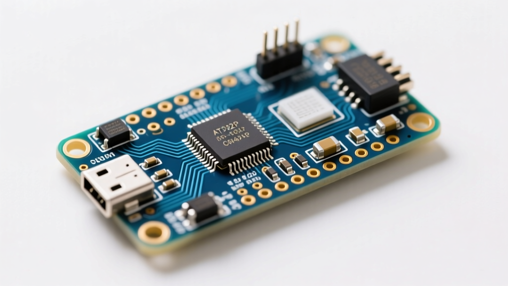
Unlike the Uno, which utilizes through-hole components and a spacious DIP-28 microcontroller, the Nano compresses the entire ATmega328P-AU (TQFP-32) ecosystem into a 0.7 x 1.7-inch footprint. This density forces specific compromises in power regulation, thermal management, and USB-to-Serial routing. By dissecting the official and clone schematics, we can uncover the exact component values, failure modes, and design limitations that dictate how this board behaves in real-world applications.
The Brain: ATmega328P-AU Microcontroller Core
At the heart of the classic Nano is the Microchip ATmega328P-AU, a 32-pin TQFP surface-mount microcontroller operating at 5V and 16MHz. The schematic reveals a strict adherence to Atmel/Microchip's hardware design guidelines, particularly regarding decoupling and analog reference isolation.
- VCC and AVCC Decoupling: The schematic shows 100nF (0.1µF) ceramic capacitors placed as close as physically possible to the VCC and AVCC pins. This creates a local charge reservoir to handle the nanosecond current spikes generated when internal logic gates switch states.
- AREF Isolation: The Analog Reference (AREF) pin is typically left floating or connected to a 100nF capacitor to ground. The schematic explicitly avoids tying AREF directly to the 5V rail, which would cause severe noise injection into the 10-bit ADC readings during high-frequency digital switching.
- Unused Pins: To minimize electromagnetic interference (EMI) and parasitic capacitance, unused I/O pins on the TQFP-32 package are configured as inputs with internal pull-up resistors enabled via software, rather than being hard-tied to VCC or GND on the PCB.
USB-to-Serial Interface: The Clone Divergence
One of the most significant deviations between the official Arduino Nano schematic and the ubiquitous third-party clones lies in the USB-to-Serial bridge. Historically, the official design utilized the FTDI FT232RL. However, due to licensing costs and supply chain shifts over the last decade, the market has standardized on the WCH CH340 series.
| Feature | Official (FT232RL) | Clone V1 (CH340G) | Clone V2 (CH340C) |
|---|---|---|---|
| IC Cost (2026) | ~$4.50 | ~$0.60 | ~$0.80 |
| External Crystal | No (Internal) | Yes (12MHz) | No (Internal) |
| Driver Requirement | Native / FTDI | CH340 Driver | CH340 Driver |
| Max Baud Rate | 3 Mbps | 2 Mbps | 2 Mbps |
If you are examining a modern clone schematic, you will likely see the CH340C. Unlike the older CH340G, which required an external 12MHz crystal and two 22pF load capacitors, the CH340C integrates the clock source internally. This saves valuable PCB real estate and reduces the BOM (Bill of Materials) cost. For developers writing custom drivers or debugging serial timeouts, the SparkFun CH340 Driver Guide remains the definitive resource for managing the latency timers inherent to these clone ICs.
Power Delivery and the Thermal Bottleneck
The power tree in the Arduino Nano schematic is a masterclass in compact, albeit thermally constrained, design. The board supports two primary power inputs: USB 5V and the VIN pin (recommended 7V to 12V). Understanding the interaction between these rails is crucial for preventing catastrophic hardware failure.
The MBR0520 Schottky Diode
When powered via USB, the 5V line passes through a resettable PTC polyfuse (typically rated at 500mA) and then through an MBR0520 Schottky diode. This diode serves a critical protective function: it prevents back-powering the host computer's USB port if a higher voltage is simultaneously applied to the 5V pin. The MBR0520 exhibits a forward voltage drop of approximately 0.38V at 500mA, meaning the actual VCC rail sits at roughly 4.62V when drawing maximum USB current.
The 5V LDO and Thermal Shutdown
When powering the Nano via the VIN pin, the voltage is routed to a 5V Low Dropout Regulator (LDO). Official schematics often specify the MIC5205-5.0BM5 or LP2985 in a SOT-23-5 package. This is where the schematic reveals a severe thermal limitation.
Engineering Warning: The SOT-23-5 package has a junction-to-ambient thermal resistance ($\theta_{JA}$) of roughly 160°C/W. If you supply 12V to VIN and draw just 100mA from the 5V rail, the LDO must dissipate 0.7W of heat. This results in a junction temperature rise of 112°C above ambient, instantly triggering the IC's internal thermal shutdown protection. For continuous draws exceeding 50mA, always power the Nano via the USB or 5V pins, bypassing the onboard LDO entirely.
For a complete visual breakdown of these power routing traces and pin mappings, refer to the Official Arduino Nano Pinout and Schematic PDF.
Clock Sources and the Auto-Reset Circuit
The timing and programming circuits on the Nano rely on precise passive components that are frequently damaged during aggressive rework or static discharge.
The 16MHz Resonator
While early Nano revisions used a standard quartz crystal with two 22pF load capacitors, modern official boards and high-quality clones utilize a 16MHz ceramic resonator (such as the Murata CSTCE series). This integrated component contains the crystal and matching capacitors in a single SMD package, reducing parasitic trace inductance and improving startup reliability in noisy industrial environments.
The DTR Auto-Reset Mechanism
One of the most elegant features in the Arduino schematic is the auto-reset circuit, which eliminates the need to manually press the reset button when uploading code. The DTR (Data Terminal Ready) line from the USB-to-Serial IC is routed through a 100nF (0.1µF) capacitor to the ATmega328P's RESET pin.
When the Arduino IDE opens the serial port, the DTR line drops from HIGH to LOW. The 100nF capacitor acts as a differentiator, passing this sudden voltage change as a brief negative pulse to the RESET pin. This pulls the pin below the logic LOW threshold (0.2 x VCC) just long enough to trigger the bootloader, before the 10kΩ pull-up resistor returns the pin to a stable HIGH state. If your board requires manual resetting during uploads, this 100nF capacitor is almost certainly cracked or desoldered.
Schematic-Driven Troubleshooting and Failure Modes
By mapping common field failures directly to the schematic, technicians can diagnose dead Nano boards in minutes rather than hours. Here are the most frequent hardware faults observed in 2026:
- Shorted MBR0520 Diode: If a user accidentally applies 9V to the 5V pin, the MBR0520 diode takes the brunt of the reverse voltage and fails short. Symptoms include the board becoming extremely hot near the USB connector and the host PC's USB port shutting down due to overcurrent. Fix: Desolder the Schottky diode and replace it with a new MBR0520 or SS14.
- Fried 3.3V LDO: The Nano features a secondary LDO to generate 3.3V for external sensors. This regulator is typically rated for only 50mA to 150mA. Users frequently destroy this IC by connecting 3.3V ESP8266 modules that draw peak currents of 300mA during Wi-Fi transmission. Fix: Bypass the onboard 3.3V regulator and use an external AMS1117-3.3 buck module for wireless peripherals.
- Corrupted Bootloader / Missing Pull-up: The RESET pin requires a stable 10kΩ pull-up to VCC. In high-vibration environments, the solder joints on this tiny 0603 resistor can fracture, leaving the RESET pin floating. This causes the ATmega328P to randomly reset when subjected to EMI from nearby relays or motors. Fix: Inspect the 10kΩ resistor near the reset button under 10x magnification and reflow the pads.
Conclusion
The Arduino Nano schematic diagram is a blueprint of pragmatic engineering, balancing cost, size, and functionality. While it is not designed for high-current industrial control, its architecture provides invaluable lessons in power multiplexing, USB enumeration, and microcontroller decoupling. Whether you are designing a custom PCB based on the ATmega328P-AU or troubleshooting a fleet of clone boards, keeping the nuances of the CH340C serial bridge and the SOT-23-5 thermal limits in mind will save you countless hours of debugging. For further hardware specifications, always consult the Arduino Nano Documentation Hub to ensure your firmware aligns with the physical realities of the silicon.