
The Architecture: Why Bridge Arduino and ESP32?
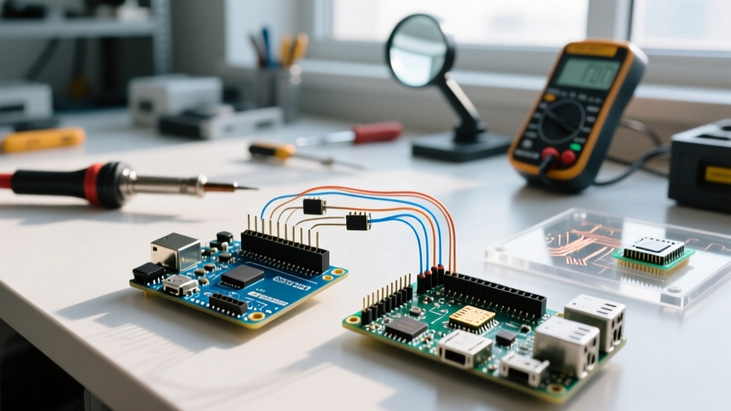
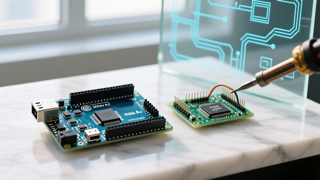
Combining an ATmega328P-based Arduino Uno R3 with an ESP32-WROOM-32 creates a powerhouse architecture for industrial and home automation IoT nodes. While the ESP32 excels at WiFi/Bluetooth stack management and dual-core processing (240 MHz), the Arduino Uno provides robust 5V I/O tolerance, stable analog-to-digital conversion for legacy sensors, and simple interrupt handling. Bridging them via an Arduino serial ESP32 UART connection allows you to offload heavy network tasks to the ESP32 while the Arduino manages precision hardware control. This dual-MCU topology is heavily favored in commercial SCADA gateways where network isolation from noisy sensor buses is critical.
Critical Hardware Warning: The 5V vs 3.3V Trap
Hardware Alert: Never connect a 5V Arduino TX pin directly to a 3.3V ESP32 RX pin. The ESP32 GPIO pins are strictly 3.3V tolerant. Exposing them to 5V logic will inject current through the internal ESD protection diodes, degrading the silicon and eventually causing permanent thermal failure of the input buffer.
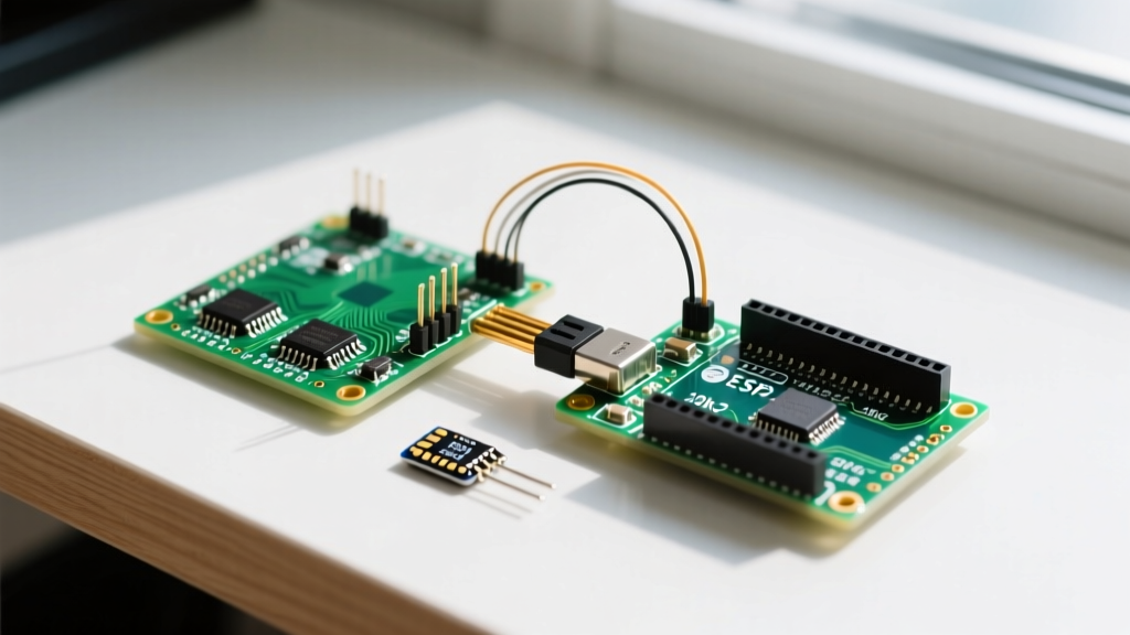
To safely establish an Arduino serial ESP32 link, you must step down the 5V logic from the Arduino's transmit (TX) line to the 3.3V receive (RX) line of the ESP32. While you can use a bidirectional logic level converter (like the BSS138 MOSFET-based modules costing around $1.50), a simple resistor voltage divider is highly effective for one-way UART telemetry and costs less than $0.10 in passive components.
Wiring Matrix: Arduino Uno R3 to ESP32-DevKitC
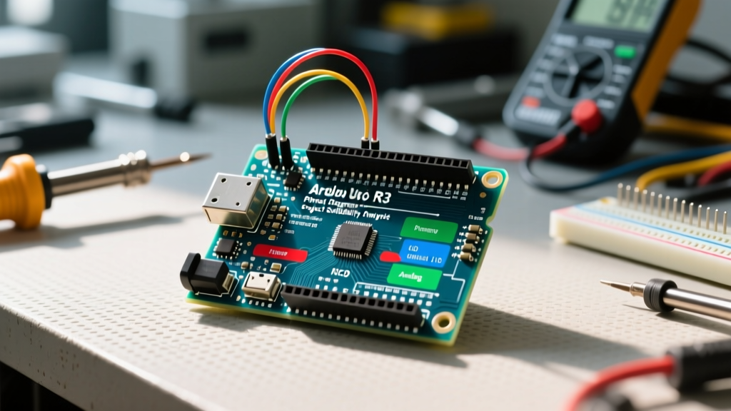
Below is the exact pinout matrix for a safe, level-shifted UART connection. We utilize the ESP32's Hardware Serial 2 (UART2) to avoid conflicts with the USB-to-UART bridge on GPIO 1 and GPIO 3.
| Signal Path | Arduino Uno R3 Pin | Intermediate Component | ESP32-DevKitC Pin |
|---|---|---|---|
| Arduino TX to ESP32 RX | Pin 11 (SoftwareSerial TX) | 1kΩ Resistor (Series) & 2kΩ Resistor (Pull-down to GND) | GPIO 16 (RX2) |
| ESP32 TX to Arduino RX | Pin 10 (SoftwareSerial RX) | Direct Connection (3.3V is read as HIGH by 5V logic) | GPIO 17 (TX2) |
| Common Ground | GND | Direct Wire (Mandatory for signal reference) | GND |
Step-by-Step UART Setup & Configuration
Step 1: Constructing the Voltage Divider
Connect the 1kΩ resistor to the Arduino TX pin (Pin 11). Connect the other end of the 1kΩ resistor to the ESP32 RX pin (GPIO 16). Finally, connect the 2kΩ resistor between the ESP32 RX pin (GPIO 16) and the common ground. This creates a voltage divider that drops the 5V HIGH signal to exactly 3.33V, safely within the ESP32's tolerance threshold. Ensure your resistors are 1/4W or 1/8W; higher wattage resistors add unnecessary parasitic inductance which can round off the square waves at high baud rates.
Step 2: Understanding ESP32 GPIO Restrictions
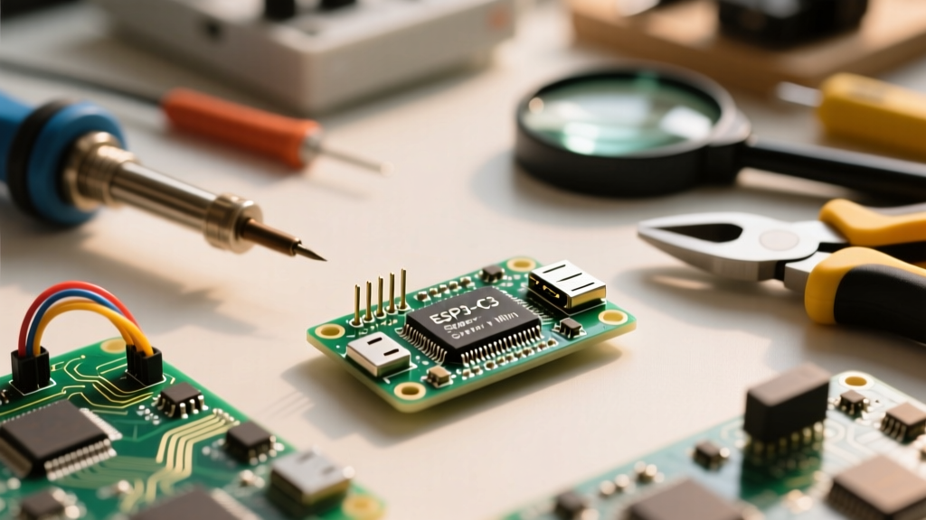
Not all ESP32 pins can be used for UART. According to the official Espressif GPIO documentation, GPIO 6 through 11 are connected to the integrated SPI flash and must never be used for serial communication. Furthermore, GPIO 1 and 3 are tied to the onboard CP2102 USB-to-UART bridge. Using them for your Arduino serial ESP32 connection will result in garbled data and boot failures. Always default to GPIO 16 (RX2) and GPIO 17 (TX2) for Hardware Serial 2.
Step 3: Baud Rate Synchronization
Both microcontrollers must initialize their serial buffers at the exact same baud rate. For short-distance UART runs (under 2 meters), 115200 bps is the standard. If you experience bit errors over longer wire runs, drop the baud rate to 9600 bps to increase the bit-width timing tolerance, as the Arduino's ceramic resonator can introduce slight clock drift compared to the ESP32's crystal oscillator.
First Project: Offloading DHT22 Telemetry
In this first project, the Arduino reads a 5V DHT22 temperature/humidity sensor and transmits a structured key-value payload via serial to the ESP32. We avoid heavy JSON libraries on the ATmega328P to save flash memory, using a simple comma-separated string instead.
Arduino Uno R3 Code (Transmitter)
We use the Arduino SoftwareSerial library to free up the hardware UART (Pins 0/1) for USB debugging via the Serial Monitor. Note: The DHT22 requires a 4.7kΩ pull-up resistor on its data line.
#include <SoftwareSerial.h>
#include <DHT.h>

SoftwareSerial espSerial(10, 11); // RX, TX
DHT dht(2, DHT22); // Sensor on Pin 2

void setup() {
  Serial.begin(115200);
  espSerial.begin(115200);
  dht.begin();
}

void loop() {
  float h = dht.readHumidity();
  float t = dht.readTemperature();

  if (!isnan(h) && !isnan(t)) {
    espSerial.print("T:");
    espSerial.print(t);
    espSerial.print(",H:");
    espSerial.println(h);
  }
  delay(2000); // DHT22 requires 2s sampling interval
}
ESP32 Code (Receiver & Parser)
#define RXD2 16
#define TXD2 17

void setup() {
  Serial.begin(115200); // USB Debug
  Serial2.begin(115200, SERIAL_8N1, RXD2, TXD2); // Hardware UART2
  Serial.println("ESP32 UART2 Listening...");
}

void loop() {
  if (Serial2.available()) {
    String payload = Serial2.readStringUntil('\n');
    int tIndex = payload.indexOf("T:");
    int hIndex = payload.indexOf(",H:");

    if (tIndex != -1 && hIndex != -1) {
      float temp = payload.substring(tIndex + 2, hIndex).toFloat();
      float hum = payload.substring(hIndex + 3).toFloat();
      Serial.printf("Received -> Temp: %.2f C, Hum: %.2f %%\n", temp, hum);
    }
  }
}
Real-World Troubleshooting & Edge Cases
- The 'Floating Ground' Error: If your ESP32 receives garbage characters (e.g., `????` or random ASCII), 90% of the time the common ground wire between the two boards is missing or has high resistance. UART is a single-ended protocol requiring a shared voltage reference. Without it, the receiver's comparator cannot accurately distinguish a logic HIGH from a logic LOW.
- ESP32 Boot Loop on Reset: If the ESP32 fails to boot when the Arduino is powered on, check your TX/RX lines. If the Arduino TX pin is pulling the ESP32 RX pin HIGH during the ESP32's boot sequence, it can interfere with the strapping pins. Ensure GPIO 16 is not acting as a boot strapping pin for your specific ESP32 module variant.
- SoftwareSerial Buffer Overflows: The Arduino Uno's SoftwareSerial library disables interrupts while transmitting. If your Arduino is simultaneously reading high-frequency encoder pulses or managing precision timing, using SoftwareSerial on the Uno will cause missed ticks. In this scenario, upgrade to an Arduino Mega 2560 or an Arduino Uno R4 Minima, both of which feature multiple hardware UARTs.
- Level Shifter Capacitance: If you opt for a cheap BSS138 logic level converter instead of a resistor divider, be aware that the parasitic capacitance of the MOSFETs can round off the square waves at 115200 baud, causing bit errors. For high-speed UART, use dedicated ICs like the TI SN74AVCH1T45 or stick to the resistor divider for short runs.
Summary of Component Costs (2026 Estimates)
| Component | Model / Specification | Approx. Cost |
|---|---|---|
| Microcontroller 1 | Arduino Uno R3 (ATmega328P) | $18.00 - $24.00 |
| Microcontroller 2 | ESP32-DevKitC V4 (WROOM-32U) | $6.50 - $9.00 |
| Sensor | Aosong DHT22 (AM2302) | $4.00 - $6.00 |
| Passives | 1kΩ & 2kΩ Resistors (1/4W) | < $0.10 |
By mastering this Arduino serial ESP32 bridge, you unlock a scalable topology. The Arduino handles the messy, electrically noisy 5V real-world hardware, while the ESP32 sits safely in the 3.3V domain, managing cloud connectivity, TLS encryption, and OTA updates without risking lockups from sensor bus faults.