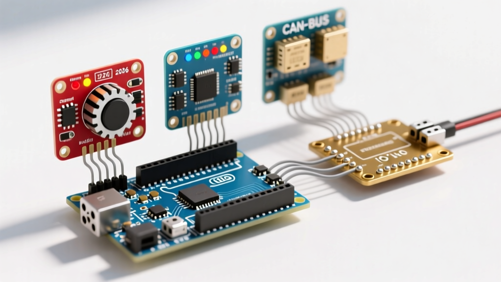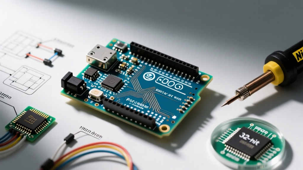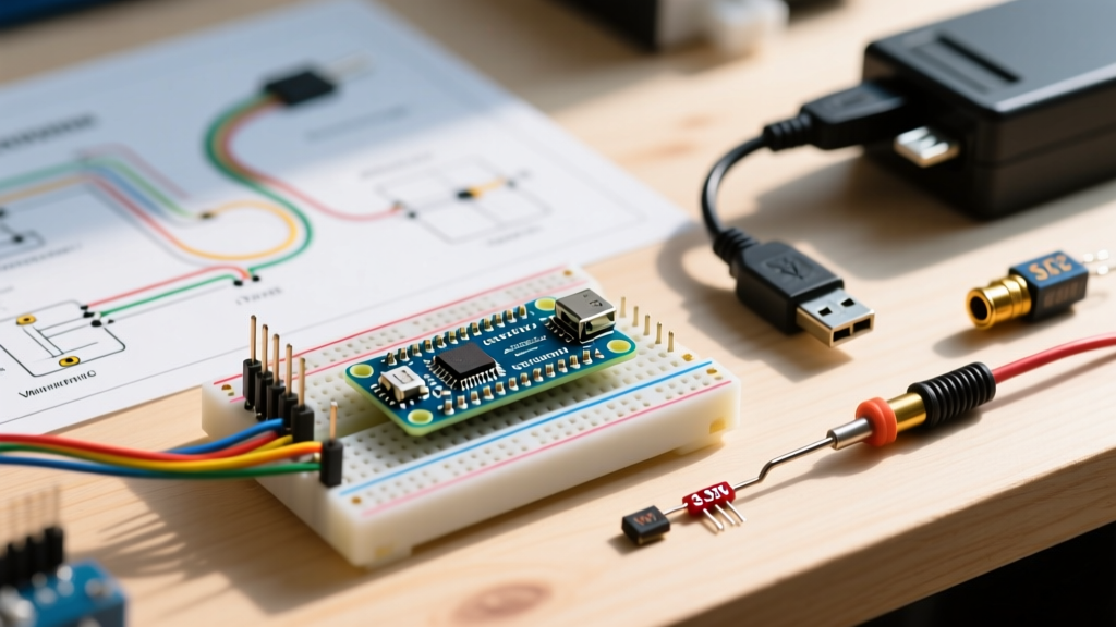

Understanding the Arduino Nano Power Architecture
When evaluating how to power Arduino Nano boards, engineers and makers must look beyond simply plugging in a USB cable. The classic Arduino Nano V3 (based on the ATmega328P) and its modern successors like the Nano Every (ATmega4809) feature flexible but unforgiving power architectures. According to the official Arduino Nano documentation, the board operates at a 5V logic level, but the underlying microcontroller can technically function between 1.8V and 5.5V depending on the clock speed.
Choosing the right power delivery method is a critical project suitability decision. A desktop weather station has vastly different thermal and efficiency requirements than a remote, solar-powered soil moisture sensor. In this analysis, we break down the four primary power injection methods, evaluating them based on efficiency, thermal limits, cost, and specific project use cases for 2026 and beyond.
Evaluating the Four Primary Power Methods
1. USB Mini-B / Micro-USB: The Prototyping Standard
The most common way to power the Nano is via the USB port. The classic V3 uses a Mini-B connector, while newer iterations and clones often use Micro-USB or USB-C. The USB line feeds directly into the board's 5V rail through a resettable PTC polyfuse (typically rated for 500mA on official boards) and a protection diode.
- Efficiency: High (nearly 100% from the USB 5V rail to the board's 5V pin, minus a ~0.3V drop across the protection diode).
- Current Limit: 500mA (standard USB 2.0 specification).
- Project Suitability: Desktop prototypes, tethered data loggers, and projects requiring serial debugging.
Edge Case Warning: Cheap, high-resistance USB cables can cause significant voltage drops. If your PC outputs 5.0V, a poor cable might deliver only 4.3V to the Nano's 5V pin. This can trigger the ATmega328P's brown-out detection (BOD), causing random reboots when servos or LEDs draw peak current.
2. 5V Pin Direct Injection: The Efficiency Hack
Bypassing the onboard voltage regulator and USB protection circuitry by injecting a clean, regulated 5V directly into the "5V" pin is the gold standard for battery-operated and high-efficiency projects. Because the classic Nano uses an AMS1117-5.0 linear regulator, bypassing it eliminates the quiescent current draw (typically 5mA to 10mA) and prevents thermal throttling.
- Efficiency: 100% (assuming your external 5V source is perfectly regulated).
- Current Limit: Limited only by the PCB trace width and your external power supply (typically safe up to 1A continuous).
- Project Suitability: Li-ion battery projects (using a 5V USB-C PD decoy or a boost converter), solar-powered arrays, and high-current LED matrices.
Critical Warning: Never inject 5V into the 5V pin while the USB cable is also connected. This backfeeds voltage into the USB host port, which can permanently damage your computer's motherboard or the Nano's USB-to-serial IC (FT232RL or CH340).
3. Vin Pin (7V-12V): Linear Regulation
The "Vin" (Voltage In) pin routes external power through the board's onboard linear regulator (usually an AMS1117-5.0 in a SOT-223 package). While the Microchip ATmega328P datasheet outlines the microcontroller's tolerances, the limiting factor here is the regulator's thermal dissipation.
Linear regulators burn excess voltage as heat. The formula for power dissipated as heat is: P = (Vin - 5V) × Current. If you supply 12V via Vin and your project draws 200mA, the regulator must dissipate 1.4 Watts of heat. The SOT-223 package lacks a dedicated heatsink and will hit its thermal shutdown threshold (around 125°C junction temperature) rapidly under these conditions.
- Efficiency: Poor (drops to ~41% at 12V input).
- Current Limit: ~800mA absolute maximum, but practically limited to ~150mA at 12V input due to thermal constraints.
- Project Suitability: Automotive applications (12V car batteries) where current draw is minimal (e.g., just the MCU and a few sensors), or 9V battery setups drawing less than 50mA.
4. 3.3V Direct Injection: Ultra-Low Power IoT
For advanced users building ultra-low-power IoT nodes, powering the Nano directly via the 3.3V pin is a highly effective, albeit unsupported, technique. According to SparkFun's guide on voltage regulators and Microchip's specifications, the ATmega328P can run safely at 3.3V, provided the clock speed is reduced to 8MHz (down from the default 16MHz).
To execute this, you must inject regulated 3.3V into the 3.3V pin (which bypasses the onboard 3.3V LDO) and re-flash the bootloader using an ISP programmer to set the fuses for an 8MHz internal oscillator and lower the Brown-Out Detection (BOD) to 1.8V.
- Efficiency: Exceptional when paired with a 3.3V LDO or direct 2S LiFePO4 battery.
- Project Suitability: Deep-sleep wearable devices, remote LoRaWAN nodes, and coin-cell battery applications.
Project Suitability Matrix
To streamline your design phase, use the following decision matrix to select the optimal power method based on your specific project parameters.
| Project Type | Recommended Power Method | Recommended Hardware (2026) | Estimated Cost |
|---|---|---|---|
| Desktop Serial Monitor | USB (Mini-B/Micro) | Standard USB Cable | $2 - $5 |
| High-Current LED/Robotics | 5V Pin Direct Injection | LM2596 Buck Converter Module | $1.50 - $3.00 |
| Automotive Telemetry | Vin Pin (with external buck) | Recom R-785.0-1.0 Switching Regulator | $8.00 - $12.00 |
| Remote LoRaWAN Sensor | 3.3V Direct (8MHz Mod) | HT7333 LDO + 18650 Li-ion | $4.00 - $6.00 |
| Wearable / Coin Cell | 3.3V Direct (8MHz Mod) | CR2032 Holder (Direct to 3.3V pin) | $0.50 - $1.00 |
Critical Failure Modes and Edge Cases
When designing permanent installations, theoretical power limits often differ from real-world physics. Here are the most common failure modes encountered when powering the Arduino Nano:
The "Vin Thermal Death Spiral"
Many beginners connect a 12V wall adapter to the Vin pin and then attach a 5V relay module and an LCD screen. The combined current draw easily exceeds 250mA. The AMS1117-5.0 regulator overheats, triggering its internal thermal protection. The board reboots. As it cools, it turns back on, overheats, and reboots again. This endless loop degrades the regulator over time. Solution: Always use a switching buck converter (like the TPS5430 or LM2596) to step 12V down to 5V, and inject it into the 5V pin.
USB Ground Loops in Industrial Settings
If your Nano is powered via USB from a PC, but also connected to high-voltage industrial sensors or motors sharing a common ground, you risk creating a ground loop. This can push lethal currents backward through the USB ground trace, instantly vaporizing the PCB trace or destroying the PC's USB controller. Solution: Use an opto-isolator for sensor inputs or a digital isolator module (like the ISO7240) on the serial lines, and power the Nano via an isolated DC-DC converter.
The Clone Board Lottery
While an official Arduino Nano costs around $24 in 2026, third-party clones from marketplaces like AliExpress or Amazon often sell for $3 to $5. These clones frequently substitute the AMS1117-5.0 with cheaper, lower-spec LDOs that lack adequate thermal shutdown protection, or they use counterfeit CH340 USB-to-serial chips that fail under high-temperature soldering. If using clones for mission-critical Vin power injection, always test the regulator's thermal threshold with a thermal camera before deployment.
Expert Verdict: Choosing Your Power Path
"The Arduino Nano's flexibility is its greatest strength, but its onboard linear regulator is its greatest weakness. Treat the Vin pin as a last resort for low-current prototyping, not a permanent power solution for high-draw deployments."
Ultimately, figuring out how to power Arduino Nano hardware comes down to respecting the physics of linear regulation. For 90% of permanent, field-deployed projects, bypassing the onboard circuitry and utilizing the 5V pin with an external switching buck converter offers the best balance of reliability, cost, and thermal safety. For ultra-low-power IoT edge devices, the 3.3V injection method remains an unmatched, albeit advanced, technique for maximizing battery life.
Frequently Asked Questions
Can I power the Arduino Nano with a 9V battery?
Yes, you can connect a 9V battery to the Vin pin. However, standard 9V alkaline batteries have a relatively low capacity (around 400-500mAh) and high internal resistance. Because the Nano's idle current is roughly 20mA (and higher with sensors), a 9V battery will likely be depleted in less than 24 hours. For long-term 9V applications, use a Lithium 9V or step down a larger Li-ion pack.
What happens if I accidentally supply 6V to the 5V pin?
Supplying 6V directly to the 5V pin bypasses the voltage regulator and feeds directly into the ATmega328P's VCC rail. The absolute maximum rating for the microcontroller is 6V. While it may survive briefly, you risk permanent silicon degradation, erratic ADC (Analog-to-Digital Converter) readings, and potential destruction of any connected 5V sensors. Never exceed 5.5V on the 5V pin.
Does the Arduino Nano Every have the same power limitations?
The Nano Every (ATmega4809) uses a different power management IC and a more efficient architecture than the classic V3. While it still features a linear regulator for the Vin pin, its overall quiescent current is lower. However, the fundamental physics of linear heat dissipation still apply; for high-current projects, injecting regulated 5V into the 5V pin remains the recommended best practice across the entire Nano family.