
Understanding Arduino Nano Voltage Input Pathways
When designing embedded systems around the classic Arduino Nano, managing the Arduino Nano voltage input is the most common point of catastrophic failure. Unlike larger boards with dedicated power management ICs and massive heatsinks, the Nano relies on a tiny, surface-mount linear voltage regulator. Pushing the wrong voltage into the wrong pin will instantly vaporize the regulator or the ATmega328P microcontroller.
To master power delivery, you must understand the three distinct power pathways available on the board's pinout and how they interact with the onboard protection diodes and regulators. Misunderstanding these pathways is the primary reason DIY projects fail in the field when moved from a USB tether to a standalone battery or wall-wart supply.
The Three Power Entry Points
| Pin / Port | Recommended Voltage | Absolute Maximum | Internal Routing & Protection |
|---|---|---|---|
| USB (Mini-B / Type-C) | 5.0V DC | 5.5V | Routes through a 500mA resettable PTC polyfuse and a Schottky diode (typically MBR0520) to the 5V rail. Expect a 0.3V drop across the diode. |
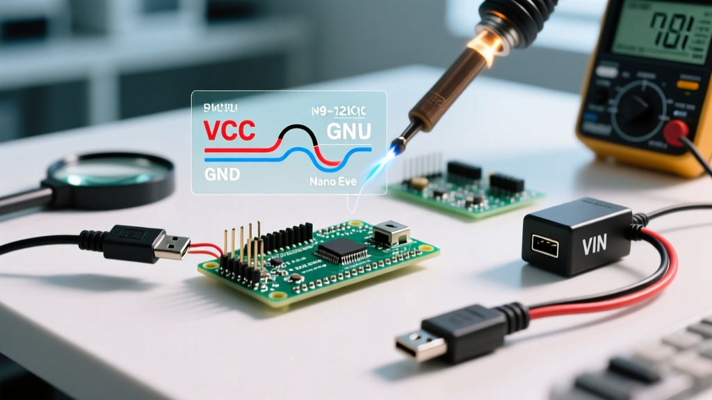
| VIN Pin | 7V to 12V | 20V (Brief) | Feeds the onboard linear regulator. Protected by a reverse-polarity diode (1N4007 or similar) which introduces a ~0.7V forward voltage drop. |
| 5V Pin | 5.0V DC | 5.5V | Direct connection to the 5V rail. Bypasses all regulators, fuses, and protection diodes. |
The Linear Regulator Bottleneck: Thermal Math
The most misunderstood aspect of the Arduino Nano voltage input is the VIN pin. Many beginners assume that because the board accepts up to 20V on VIN, they can safely power a 12V relay module and a strip of WS2812B LEDs directly from the Nano's 5V pin while feeding 12V into VIN. This is a recipe for the "magic smoke" failure mode.
The Nano uses a linear regulator. Linear regulators dissipate excess voltage as heat. The power dissipated ($P_D$) is calculated as:
$P_D = (V_{IN} - V_{OUT}) \times I_{LOAD}$
Let us run a real-world scenario. You connect a 12V wall adapter to the VIN pin. Your circuit draws 150mA from the 5V rail (e.g., the microcontroller, a few sensors, an I2C OLED display, and the onboard CH340 USB-to-Serial chip).
- $V_{IN} = 12V$
- $V_{OUT} = 5V$
- $I_{LOAD} = 0.15A$
$P_D = (12 - 5) \times 0.15 = 1.05 \text{ Watts}$.
Dissipating 1.05W through a tiny SOT-223 or SOT-89 surface-mount package without active cooling is disastrous. According to the AMS1117 Datasheet, the thermal resistance ($\theta_{JA}$) of the SOT-223 package is roughly 100°C/W. A 1.05W dissipation results in a temperature rise of 105°C above ambient. In a 25°C room, the regulator case will hit 130°C. This triggers internal thermal shutdown (usually set at 150°C junction temperature), causing your Nano to randomly reset under load.
Genuine vs. Clone Hardware in 2026
In 2026, the maker market is heavily saturated with clone boards. A genuine Arduino Nano (priced around $24.00 to $27.00) typically uses high-quality linear regulators with robust copper pours acting as heatsinks. However, $3.50 to $5.00 clone boards dominate the DIY space, and their voltage input handling varies wildly based on Bill of Materials (BOM) cost-cutting.
Common Clone Regulators and Their Limits
- AMS1117-5.0 (SOT-223): The most common clone regulator. Capable of 800mA continuous current, but thermally limited to ~1W without adequate PCB copper. Dropout voltage is 1.1V to 1.3V, meaning you need at least 6.3V on VIN to maintain a stable 5V output.
- ME6211C50 (SOT-23-5): Found on ultra-cheap "Nano V3.0" clones. This is a low-power LDO meant for battery devices. It maxes out around 500mA and has terrible thermal dissipation due to the microscopic package. Feeding 9V into VIN with a mere 100mA load will overheat this chip in seconds.
- CH340G vs CP2102: While these are USB-to-Serial chips, they also draw current from the 5V rail. The CH340G draws roughly 30mA to 40mA, adding to your thermal load if powered via VIN. If you are operating near the thermal edge, disabling the USB chip by cutting the VCC trace can save critical milliwatts of heat dissipation.
The 5V Pin Danger Zone: Bypassing Protection
Powering the Nano via the "5V" pin is highly efficient because it completely bypasses the lossy linear regulator. However, it is entirely unforgiving. According to the Microchip ATmega328P Datasheet, the absolute maximum voltage on the VCC pin is 6.0V. Operating at 5.5V or higher degrades the silicon and can permanently latch up the internal SRAM.
Furthermore, the 5V pin lacks reverse polarity protection. If you accidentally swap Ground and 5V on your breadboard power supply, current will flow backward through the board's 5V rail, instantly destroying the ATmega328P and the USB interface chip. There is no polyfuse to save you here.
When to use the 5V pin: Only when you have a highly regulated, clean 5.0V source (like a dedicated buck converter or a laboratory power supply) and you are absolutely certain of your wiring polarity.
Recommended Power Architectures for Nano Projects
To ensure long-term reliability and avoid thermal throttling, abandon the idea of using the Nano's onboard regulator for high-current loads. Instead, use external DC-DC step-down (buck) converters.
Architecture 1: The High-Current Sensor Hub
- Use a 9V or 12V DC power supply.
- Connect the supply to an MP1584EN buck converter module (cost: ~$1.50). Adjust the module's onboard potentiometer with a multimeter to output exactly 5.0V.
- Feed the 5.0V output directly into the Nano's 5V pin.
- Tap the 5V rail on the breadboard to power high-current peripherals (relays, LED strips, servos).
Result: The Nano's onboard regulator handles 0W of dissipation. The MP1584EN operates at >90% efficiency, remaining cool to the touch even at 2A loads, completely eliminating thermal shutdown resets.
Architecture 2: LiPo Battery Portability
If you are building a portable data logger, do not use a 7.4V (2S) LiPo pack into the VIN pin. The dropout voltage and heat generation will drain your battery rapidly and waste energy as heat. Instead, use a single-cell (3.7V) LiPo battery paired with a MT3608 boost converter set to 5.0V, feeding the 5V pin. Alternatively, use a dedicated 5V USB power bank connected to the Mini-B/Type-C port, leveraging the board's existing USB polyfuse for short-circuit protection.
Troubleshooting Voltage Input Failures
If your Nano is behaving erratically, the power delivery network is the prime suspect. Here is a professional diagnostic checklist:
- Random Resets Under Load: The regulator is hitting thermal shutdown. Measure the VIN current and calculate your thermal dissipation. If the regulator is too hot to keep your finger on for more than 3 seconds, you are exceeding safe continuous limits. Switch to a buck converter.
- Brown-Out Detection (BOD) Triggering: If the 5V rail dips below 4.3V momentarily, the ATmega328P's internal BOD will reset the chip. Clone boards often ship with the BOD fuse set to 2.7V, but voltage sags from cheap AMS1117 regulators under transient motor loads can still cause logic faults. Add a 470µF electrolytic capacitor and a 0.1µF ceramic capacitor directly across the 5V and GND pins on your breadboard to handle transient current spikes.
- USB Disconnects and Backpowering: If powering via VIN and USB simultaneously, ensure the VIN voltage does not back-feed into the USB port. The onboard Schottky diode prevents this, but if the diode fails short, 12V could travel back up your USB cable and destroy your computer's motherboard. Always use a high-quality USB hub when testing high-voltage VIN setups.
Final Verdict on Nano Power Delivery
Mastering the Arduino Nano voltage input requires respecting the physical limits of surface-mount linear regulators. While the official Arduino Nano documentation states a recommended VIN input of 7-12V, real-world thermal dynamics dictate that you should keep the voltage differential between VIN and 5V as low as possible, or bypass the regulator entirely using a high-efficiency external buck converter. By treating the Nano strictly as a logic controller rather than a power distribution hub, your embedded projects will achieve rock-solid stability in the field.