
The Arduino Nano Uno Migration: Why Port Your Project?
In the embedded prototyping space, developers frequently need to transition a proof-of-concept into a compact deployment, or vice versa. The Arduino Nano Uno migration is one of the most common hardware transitions in the maker and engineering community. While both boards historically share the same ATmega328P microcontroller core, their physical implementations, power delivery networks, and peripheral routing differ in ways that can silently break a project if overlooked.
Whether you are shrinking an Arduino Uno Rev3 design to fit inside a weatherproof enclosure using a Nano, or scaling up a Nano breadboard prototype to leverage Uno shields, understanding the silicon-level and board-level discrepancies is critical. This guide provides a deep-dive technical framework for migrating between these two platforms without falling victim to common hardware traps.
Core Hardware & Microcontroller Differences
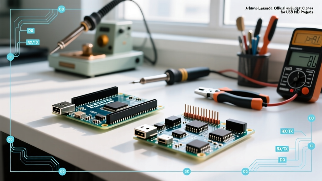
At first glance, a classic Nano and Uno both run at 16MHz and feature 32KB of Flash memory. However, the packaging of the microcontroller dictates the available I/O. The Uno utilizes a DIP-28 (Dual In-line Package) ATmega328P, while the Nano uses the QFP-32 (Quad Flat Package) surface-mount variant.
| Feature | Arduino Uno (R3 / Clone) | Arduino Nano (V3 / Clone) |
|---|---|---|
| MCU Package | ATmega328P-PU (DIP-28) | ATmega328P-AU (QFP-32) |
| Digital I/O Pins | 14 (of which 6 provide PWM) | 14 (of which 6 provide PWM) |
| Analog Input Pins | 6 (A0 - A5) | 8 (A0 - A7) |
| USB-to-Serial IC | ATmega16U2 (Native USB) | FT232RL or CH340G (Clone) |
| Form Factor | 68.6 x 53.4 mm (Shield Compatible) | 45 x 18 mm (Breadboard Friendly) |
The QFP-32 Advantage: Extra Analog Channels
Because the QFP-32 package exposes more physical pins from the silicon die than the DIP-28 package, the Nano breaks out two additional analog pins: A6 and A7. However, this introduces the most notorious failure mode in Nano Uno migrations.
The A6 and A7 Trap: Analog-Only Limitations
When migrating code from a Nano (where you might have used A6 or A7 for sensor inputs) to an Uno, you will immediately realize the Uno lacks these pins. But the reverse migration—moving from Uno to Nano and attempting to use A6/A7 as digital I/O—is where projects fail.
Critical Engineering Note: On the ATmega328P QFP-32 package, ADC6 and ADC7 are connected only to the analog multiplexer. They lack the digital input buffer and output latch circuitry. You cannot use
digitalWrite(),digitalRead(), orpinMode()on A6 or A7.
If your migration requires a digital pin and you attempt to use A6 to drive an LED or read a push-button, the pin will remain in a high-impedance state. According to the official Arduino analog pin documentation, attempting to use these pins digitally will result in floating, unpredictable readings. If you need 16 digital I/O lines, you must utilize an I/O expander (like the MCP23017) or migrate to an Arduino Nano Every, which uses the ATmega4809 and supports digital I/O on all analog pins.
Power Delivery Networks: Voltage Regulators and Limits
Power delivery is where the physical size of the board severely impacts thermal management and current capacity. When migrating a project that draws significant current from the 5V rail, you must recalculate your power budget.
USB Power Constraints
- Arduino Uno: Features a resettable PTC polyfuse on the USB line rated for 500mA. The PCB traces are wide, allowing safe continuous draws of ~400mA from the 5V pin when USB-powered.
- Arduino Nano: The USB 5V line passes through a Schottky diode (typically an SS14 or 1N5819 on genuine boards) to prevent back-feeding. This diode introduces a voltage drop (approx. 0.3V) and is thermally limited. Continuous draws exceeding 300mA from the Nano's 5V pin via USB can overheat the diode and cause brownouts.
Vin and Linear Regulator Thermal Limits
If you are powering your project via the Vin pin or the barrel jack (Uno only), the onboard linear regulator (usually an NCP1117-5.0) must dissipate the excess voltage as heat. The Uno's large PCB acts as a heatsink. The Nano's tiny PCB does not. Supplying 12V to a Nano's Vin pin while drawing just 150mA from the 5V rail will cause the regulator to hit its thermal shutdown threshold (~150°C junction temperature) within minutes. For Nano deployments requiring >100mA at 5V, always use a synchronous buck converter (like an LM2596 module) to step down external power to 5V before feeding it into the Nano's 5V pin directly.
USB-to-Serial Interfaces and Bootloader Quirks
The Uno utilizes an ATmega16U2 programmed as a USB-to-Serial converter. This chip enumerates natively on all modern operating systems without custom drivers and supports advanced features like HID (Keyboard/Mouse emulation) via the HoodLoader2 firmware.
The Arduino Nano, however, relies on an FTDI FT232RL (on genuine boards) or a WCH CH340G (on 90% of third-party clones in the 2026 market). When migrating to a clone Nano, you must install the CH340 signed drivers for Windows or macOS. Furthermore, the auto-reset circuit—which relies on a 100nF capacitor coupling the DTR line from the USB IC to the ATmega328P reset pin—is sometimes omitted on ultra-cheap Nano clones. If your Nano requires you to manually press the reset button exactly when the IDE says "Uploading," the 100nF capacitor is missing. Soldering a 100nF ceramic capacitor between the DTR pad and the Reset pin will permanently fix this migration headache.
Timing Drift: Quartz Crystals vs. Ceramic Resonators
For time-sensitive applications (e.g., SoftwareSerial baud rates, PID control loops, or RTC synchronization), the clock source matters. Genuine Unos and Nanos use a 16.000 MHz Quartz Crystal with a ±30 PPM tolerance. However, to cut costs, many modern Nano clones use a 16 MHz Ceramic Resonator with a ±0.5% (5000 PPM) tolerance. Over a 24-hour period, a ceramic resonator can drift by over 10 seconds compared to a quartz crystal. If your migration involves moving from a genuine Uno to a clone Nano for a data-logging application, you must implement NTP synchronization (via an ESP8266 co-processor) or swap the resonator for a quartz crystal.
Step-by-Step Migration Checklist
Follow this actionable checklist to ensure a seamless hardware transition:
- Audit A6/A7 Usage: Search your codebase for
A6orA7. If migrating to Uno, reroute these to A0-A5. If migrating to Nano and using them digitally, rewrite logic to use analog thresholding (analogRead() > 512) or add an external pull-up/pull-down resistor network. - Recalculate 5V Current Draw: Sum the maximum current draw of all sensors and modules. If >300mA, bypass the Nano's onboard USB diode/regulator and use an external buck converter.
- Verify USB Drivers: Check Device Manager (Windows) or System Information (macOS) to identify the USB-Serial chip. Install CH340 drivers if the VID/PID matches WCH.
- Test the Auto-Reset Circuit: Perform a test upload. If manual resetting is required, verify the presence of the 100nF DTR-Reset capacitor.
- Check Shield Pin Alignment: If adapting a Nano to an Uno shield using jumper wires, ensure the analog headers are aligned correctly. The Nano's analog pins are spaced differently on some clone boards, which can shift the A0-A5 alignment by one pin, feeding 5V directly into a sensor's analog output and destroying the MCU.
Summary
Migrating between the Arduino Nano and Uno is rarely a simple "plug-and-play" swap when moving beyond basic LED blinking. By respecting the analog-only nature of A6/A7, managing the Nano's strict thermal and current limits, and accounting for USB-serial and clock source discrepancies, you can ensure your embedded project survives the transition from prototype to deployment.