
Why the Arduino Nano is the Ultimate Breadboard Microcontroller
When transitioning from pre-assembled starter kits to custom prototyping, the Arduino Nano remains the undisputed champion of solderless breadboard projects. Unlike the Arduino Uno, which requires bulky jumper wires to connect to a breadboard, the Nano features a DIP-30 (Dual In-line Package) footprint. Measuring just 18mm x 45mm, it plugs directly into standard solderless breadboards, leaving maximum real estate for your sensors, resistors, and integrated circuits.
As of 2026, the official Arduino Nano (featuring the ATmega328P microcontroller and ATmega16U2 USB-to-serial chip) retails for approximately $22.50. However, high-quality third-party clones utilizing the CH340G USB-to-serial chip are widely available for $4.00 to $6.00. Both variants share the exact same physical dimensions and pinouts, making them universally compatible with standard prototyping workflows.
Physical Placement: Mastering the Center Trench
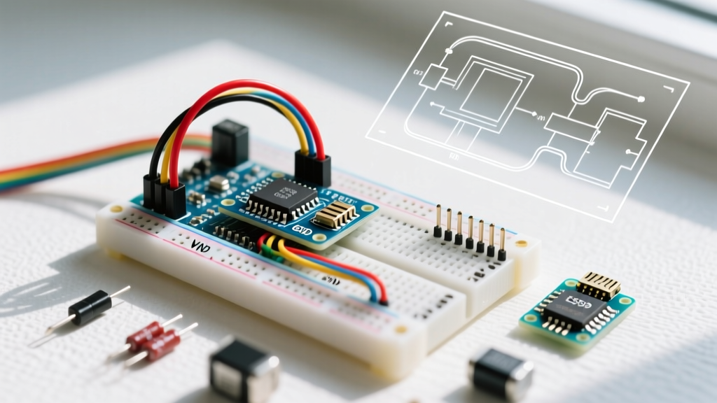
The most critical step in an Arduino Nano breadboard setup is proper physical alignment. Standard solderless breadboards (like the ubiquitous 830-point or 400-point models) feature a center trench designed specifically to accommodate DIP chips without shorting the pins across the board.
- Pitch Compatibility: The Nano's header pins are spaced at a standard 0.1-inch (2.54mm) pitch, perfectly matching the breadboard's internal spring clips.
- Trench Alignment: Seat the Nano so that the center trench runs directly beneath the microcontroller body. Pins 1 through 15 will sit in rows A-E (top half), and pins 16 through 30 will sit in rows F-J (bottom half).
- Wire Clearance: This placement leaves exactly one empty row of holes (row E on the top, row F on the bottom) between the Nano's pins and the main power rails. This single row of clearance is precisely what you need to insert 22 AWG solid-core jumper wires without them bending against the Nano's headers.
Step-by-Step Power and Ground Routing
Before connecting any sensors or LEDs, you must establish a clean, stable power distribution network across your breadboard. According to SparkFun's breadboard engineering guidelines, proper power rail management prevents ground loops and voltage sags.
1. Bridging the Power Rails
If you are using an 830-point breadboard, be aware that the red and blue power rails often have a physical break in the middle (indicated by a gap in the colored lines). Use a short jumper wire to bridge the top and bottom halves of both the 5V (red) and GND (blue) rails to ensure continuous power distribution across the entire board.
2. Routing Nano Power to the Rails
Connect the Nano's pins to the breadboard rails as follows:
- 5V Pin: Connect to the red (+) power rail. This supplies regulated 5V power sourced either from the USB connection or the onboard voltage regulator.
- GND Pins: The Nano has two GND pins (Pin 4 and Pin 14). Connect at least one to the blue (-) ground rail. For projects with high-current components like motors or relays, connect both to reduce ground path resistance.
- 3.3V Pin: If your project requires 3.3V logic (e.g., ESP8266 WiFi modules or certain I2C sensors), route this pin to a secondary, isolated power rail. Never connect the 5V and 3.3V rails together.
Expert Warning on the VIN Pin: The VIN pin is an input, not an output. While you can use it to power the Nano via an external battery pack (7V-12V), do not use it to power external breadboard components. Bypassing the onboard regulator by backfeeding 5V into the 5V pin while simultaneously plugging in the USB cable can destroy the USB port on your computer or fry the Nano's polyfuse.
Arduino Nano Breadboard Pinout Mapping Matrix
To streamline your wiring process, reference this mapping matrix. It assumes the Nano is placed with the USB port facing the left side of the breadboard, and the reset button facing up.
| Nano Pin | Function | Top Breadboard Row (A-E) | Bottom Breadboard Row (F-J) | Typical Use Case |
|---|---|---|---|---|
| D13 | Digital / SPI SCK | Row A, Col 15 | - | Onboard LED, SPI Clock |
| A7 | Analog Input Only | - | Row J, Col 15 | Potentiometers, LDRs |
| A0 | Analog / Digital | - | Row J, Col 8 | Sensor inputs |
| 5V | Power Output | - | Row J, Col 2 | Breadboard Red Rail |
| GND | Ground | - | Row J, Col 14 | Breadboard Blue Rail |
Note: For a complete schematic and official specifications, always refer to the official Arduino Nano hardware documentation.
Power Budget and Voltage Regulator Limits
A common beginner mistake is treating the Nano's 5V pin as an infinite power source. When powered via the USB port, the 5V pin is limited by your computer's USB port output (typically 500mA for USB 2.0) and the Nano's onboard polyfuse.
However, when powering the Nano via the VIN pin or the barrel jack (on older variants), the current passes through an onboard linear voltage regulator (usually an AMS1117-5.0 or MIC5205). Linear regulators dissipate excess voltage as heat. If you supply 9V to VIN and draw 200mA from the 5V breadboard rail, the regulator must dissipate 0.8 Watts of heat ((9V - 5V) x 0.2A). Because the Nano lacks a heatsink, the regulator will trigger its internal thermal shutdown, causing your microcontroller to randomly reset.
The 2026 Rule of Thumb: If powering via VIN, keep the input voltage between 7V and 8V, and limit your breadboard 5V rail draw to under 150mA. For high-current projects (servos, LED strips), use a dedicated buck converter module (like the LM2596) to step down external power directly to the breadboard rails, bypassing the Nano's regulator entirely.
Troubleshooting Common Nano Breadboard Failures
Even with perfect wiring, beginners frequently encounter software and hardware communication roadblocks. Here is how to resolve the most common issues:
1. 'Port Not Found' in Arduino IDE
If your computer does not recognize the Nano, you likely have a clone board using the CH340G USB-to-serial chip. Windows and macOS do not always include native drivers for this chip. Download and install the official CH340 drivers from the chip manufacturer's repository. Once installed, the board will appear as a standard COM port.
2. 'avrdude: stk500_getsync()' Upload Error
This error means the Arduino IDE cannot communicate with the bootloader. If you are using a budget clone, it likely ships with the older, slower bootloader. In Arduino IDE 2.x, navigate to Tools > Processor and change the selection from 'ATmega328P' to 'ATmega328P (Old Bootloader)'. This resolves the upload timeout in 95% of clone board scenarios.
3. Intermittent Resets and Brownouts
If your Nano resets every time a servo motor or relay activates, you are experiencing a brownout. Breadboard contacts have inherent resistance, and long jumper wires cause voltage drops. To fix this, add a 100nF (0.1µF) ceramic decoupling capacitor directly across the breadboard's 5V and GND rails, as close to the Nano as possible. This provides a localized energy reservoir to handle sudden current spikes.
Essential Tools for Your Workbench
To ensure reliable connections that won't fail mid-project, equip your workbench with the right materials:
- 22 AWG Solid-Core Wire: This is the exact diameter (0.64mm) required for standard breadboard clips. Stranded wire will fray and jam the contacts, while 20 AWG is too thick and will permanently bend the internal springs.
- Precision Wire Strippers: Tools like the Engineer PA-09 or Hakko CHP 170 allow you to strip exactly 6mm of insulation, ensuring no bare wire is exposed above the breadboard surface to cause accidental shorts.
- USB-A to Mini-B Cable: The classic Arduino Nano still utilizes the Mini-B USB connector. Do not confuse this with Micro-USB or USB-C. Keep a dedicated, high-quality data cable on hand; cheap gas-station cables often lack the internal data wires required for code uploading.
By mastering the physical placement, power distribution, and bootloader quirks of the Arduino Nano, you transform a fragile prototype into a robust, reliable testing platform. For more advanced platform comparisons, check out our guides on scaling up to the Arduino Nano Every or transitioning to ESP32 architectures for IoT applications.