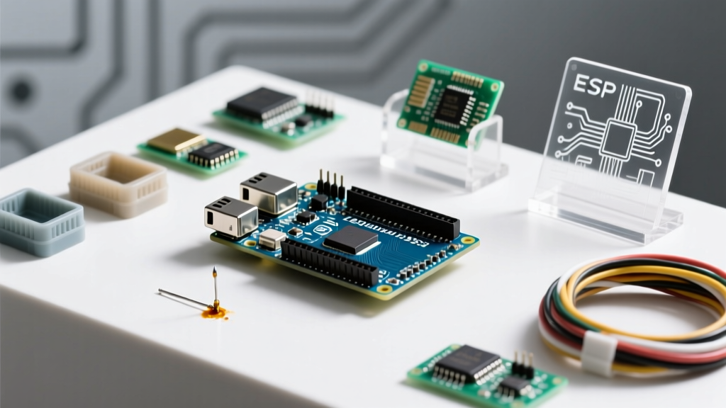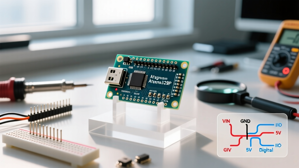

When transitioning from blinking an LED on a full-sized Arduino Uno to building compact, permanent DIY installations, the Arduino Nano is the undisputed champion of the workbench. Despite its diminutive footprint, it packs nearly the exact same capabilities as its larger sibling. However, misunderstanding the Arduino Nano specs—particularly regarding power limits, memory architecture, and USB-to-serial chip variations—is the leading cause of fried boards and stalled projects for beginners.
In this comprehensive guide, we will dissect the technical specifications of the Arduino Nano, explore the real-world limitations of its ATmega328P microcontroller, and provide actionable advice on how to integrate it into your 2026 electronics projects without falling into common hardware traps.
The Definitive Arduino Nano Specs Table
Before wiring up sensors or writing a single line of C++, you must understand the hard boundaries of the hardware. Below are the official specifications for the classic Arduino Nano (Rev 3).
| Specification | Value / Detail |
|---|---|
| Microcontroller | Microchip ATmega328P-AU |
| Operating Voltage | 5V DC (Logic Level) |
| Input Voltage (Recommended) | 7V to 12V via Vin pin |
| Input Voltage (Absolute Limits) | 6V to 20V (Risk of damage >12V) |
| Digital I/O Pins | 22 (6 provide 8-bit PWM output) |
| Analog Input Pins | 8 (A0 through A7) |
| DC Current per I/O Pin | 20 mA (40 mA absolute max, not recommended) |
| Flash Memory | 32 KB (2 KB reserved for Optiboot bootloader) |
| SRAM | 2 KB |
| EEPROM | 1 KB |
| Clock Speed | 16 MHz Crystal Oscillator |
| Physical Dimensions | 18 mm x 45 mm (0.7" x 1.77") |
| Weight | Approx. 7 grams |
For the most authoritative baseline, you can always cross-reference these figures with the official Arduino Nano Hardware Documentation.
Decoding the ATmega328P Memory Architecture
The brain of the Nano is the Microchip ATmega328P, an 8-bit AVR microcontroller. While 32KB of Flash memory sounds massive for simple sensor readings, beginners often hit a wall when they start using large string arrays, SD card libraries, or complex LCD displays.
The 2KB SRAM Bottleneck
Unlike Flash memory (which stores your compiled code), SRAM is where your variables, arrays, and runtime stack live. 2KB of SRAM is your most critical constraint. If your code declares large global arrays or uses heavy `String` objects dynamically, you will trigger a stack overflow. The microcontroller won't throw an error; it will simply reset randomly or lock up.
- Actionable Tip: Always use the `F()` macro when printing static text to the Serial monitor or LCDs. Writing `Serial.println(F("Hello World"));` forces the string to stay in Flash memory, preserving your precious 2KB of SRAM.
- Avoid Dynamic Allocation: Stay away from the `String` class in favor of standard C-style character arrays (`char[]`) to prevent memory fragmentation.
Utilizing the 1KB EEPROM
EEPROM is non-volatile memory, meaning it retains data when power is lost. It is perfect for storing calibration offsets, device states, or Wi-Fi credentials. However, each EEPROM cell has a write lifespan of roughly 100,000 cycles. Avoid writing to EEPROM inside a fast-looping `void loop()` without implementing wear-leveling or state-change checks.
Power Architecture and Thermal Failure Modes
Powering the Nano incorrectly is the fastest way to destroy the board. The Nano features three primary power entry points: the Mini-B USB port (or Micro-USB/USB-C on modern clones), the Vin pin, and the 5V pin.
Critical Warning: The 5V pin on the Nano is an output from the onboard voltage regulator when powered via USB or Vin. If you inject power directly into the 5V pin, it bypasses the regulator entirely. If your external supply exceeds 5.5V, you will instantly fry the ATmega328P chip.
The Voltage Regulator Thermal Limit
When you supply power through the Vin pin (recommended 7-12V), the onboard linear voltage regulator (typically an AMS1117-5.0 on clone boards) steps the voltage down to 5V. Linear regulators dissipate excess voltage as heat.
The formula for heat dissipation is: Power (Watts) = (Vin - 5V) * Current (Amps).
If you connect a 12V power supply to Vin and your circuit draws just 100mA (0.1A), the regulator must dissipate (12 - 5) * 0.1 = 0.7 Watts. The tiny SMD regulator on the Nano lacks a heatsink and will overheat, triggering its internal thermal shutdown. Your project will randomly reboot under load. Rule of thumb: If powering via Vin, keep the input voltage at 7V and keep total current draw under 150mA. For high-current projects (motors, LED strips), use a dedicated external 5V buck converter wired directly to the 5V pin and GND.
USB-to-Serial Interfaces: FT232RL vs. CH340
When shopping for a Nano, you will encounter two distinct versions. Understanding this spec difference will save you hours of driver troubleshooting.
- The Official FT232RL (FTDI): The genuine Arduino Nano purchased from the official store uses the FT232RL USB-to-Serial chip. It is natively supported by almost all operating systems, including Windows 11, macOS, and Linux, requiring zero manual driver installation.
- The Clone CH340G / CH340C: Third-party clone boards (often sold in packs of three for $10-$15) use the WCH CH340 chip to cut costs. While the CH340C (the newer surface-mount version) has excellent native support in modern 2026 operating systems, the older CH340G (through-hole chip) often requires you to manually download and install legacy drivers to get the COM port to show up in the Arduino IDE.
Physical Dimensions and Breadboard Integration
The Nano measures exactly 18 mm x 45 mm. Its 30 pins are spaced at standard 0.1-inch (2.54mm) pitch. However, a crucial beginner mistake involves breadboard integration.
Because the Nano is exactly 15 pins wide, plugging it directly into the center trench of a standard 830-point solderless breadboard leaves only one row of holes exposed on the bottom side. This makes it nearly impossible to wire ground or power to the bottom pins.
The Fix: Always use a breadboard that has a wider center trench, or intentionally leave the Nano hanging slightly off the edge of the board. Alternatively, solder standard male header pins to the Nano, but use female-to-male jumper wires for prototyping to preserve your breadboard's usable real estate.
Expanding the Horizon: Nano Variants
As your projects evolve, the classic 5V ATmega328P might not suffice. Arduino has released several boards in the exact same 18x45mm footprint:
- Arduino Nano Every: Upgrades the brain to the ATmega4809. It offers more flash (48KB) and SRAM (6KB) while maintaining 5V logic. It is a drop-in hardware replacement for most classic Nano projects.
- Arduino Nano 33 IoT: Features a 32-bit ARM Cortex-M0+ (SAMD21) and an ESP32-based NINA-W10 Wi-Fi/Bluetooth module. Warning: This board operates at 3.3V logic. Connecting 5V sensors directly to its I/O pins will destroy the microcontroller. Always use logic level shifters when mixing 5V and 3.3V ecosystems.
FAQ: Common Beginner Questions on Nano Specs
Can I use the 3.3V pin to power external sensors?
The 3.3V pin on the classic Nano is an output from the internal regulator of the FT232RL (or CH340) USB chip. It is strictly limited to roughly 50mA. It is perfect for low-power I2C sensors or pulling up logic lines, but it will brownout if you attempt to power an RF transmitter or a large OLED display from it.
Why does my Nano have an A6 and A7 pin, but my Uno doesn't?
The ATmega328P chip natively supports 8 analog channels. The full-sized Arduino Uno only breaks out A0 through A5 to its headers. The Nano, utilizing its tight 30-pin layout, breaks out all 8, giving you A6 and A7. Note that on the Nano, A6 and A7 are strictly analog inputs; they cannot be used as digital I/O pins or configured with internal pull-up resistors.
Is it safe to draw 40mA from a single I/O pin?
While the Microchip datasheet lists 40mA as the "Absolute Maximum" rating for a single I/O pin, operating at this limit degrades the silicon over time and risks permanent damage to the port register. Furthermore, the total current drawn across all I/O pins combined must not exceed 200mA. Always use a logic-level MOSFET or a BJT transistor to switch loads requiring more than 20mA.