
The 'Shield' Misconception: Understanding the Nano Form Factor
When makers first search for an Arduino Nano shield, they often encounter a frustrating physical reality: the Nano does not support standard stacked shields designed for the Arduino Uno. While the Uno utilizes a 1.9-inch wide female header layout for stacking, the Nano uses a 15-pin Dual In-line Package (DIP) footprint with a 0.6-inch (15.24 mm) row spacing and a 0.1-inch (2.54 mm) pin pitch. Therefore, a 'Nano shield' is technically an expansion board or adapter that the Nano plugs into, rather than a board that stacks on top of it.
As of 2026, the Arduino Nano ecosystem has fractured into multiple architectures, ranging from the classic 5V ATmega328P to the 3.3V ARM Cortex-M4 and RP2040 variants. Selecting the right expansion hardware requires a deep understanding of logic levels, power delivery, and mechanical tolerances. This guide dissects the anatomy of Nano expansion boards, evaluates official versus third-party options, and outlines critical failure modes to avoid in your next embedded project.
Arduino Nano Variant Compatibility Matrix
Before purchasing any I/O adapter or motor carrier, you must verify the logic voltage of your specific Nano board. Plugging a 3.3V board into a 5V-tolerant shield without level shifting will permanently destroy the microcontroller's GPIO pins.
| Nano Variant | MCU Core | Logic Level | Shield Compatibility Notes |
|---|---|---|---|
| Nano Classic / Clone | ATmega328P (AVR) | 5V | Native 5V I/O. Compatible with almost all generic 5V expansion boards and legacy Uno shields via adapter. |
| Nano Every | ATmega4809 (AVR) | 5V | Pinout matches Classic, but I2C/SPI alternate functions differ. Verify shield reliance on specific hardware interrupts. |
| Nano 33 IoT / BLE | nRF52840 / SAMD21 | 3.3V | CRITICAL: Requires 3.3V shields or bidirectional logic level shifters. 5V I/O will fry the MCU. |
| Nano RP2040 Connect | RP2040 (Dual Cortex-M0+) | 3.3V | Same 3.3V restriction as 33 IoT. High-speed SPI shields must account for RP2040's 3.3V IO bank limits. |
Official vs. Third-Party Nano Expansion Boards
1. The Arduino Nano Motor Carrier (ABX00041)
For robotics and kinetic projects, the Arduino Nano Motor Carrier is the gold standard. Priced around $28 to $32, this official board breaks out the Nano's pins while integrating a dedicated motor driver IC capable of handling two DC motors (up to 10A peak combined) or one stepper motor.
- Power Delivery: Features a robust external power terminal block (6V to 24V DC) with an onboard switching regulator that can back-power the Nano.
- I/O Expansion: Includes dedicated 3-pin headers for servos, standard I2C passthrough, and an integrated IMU (accelerometer/gyroscope) for closed-loop motion control.
- Edge Case Warning: The onboard 5V regulator has a strict thermal limit. If you are drawing more than 500mA continuously from the 5V rail to power external sensors, you must implement an external BEC (Battery Eliminator Circuit) to prevent thermal shutdown.
2. Generic Nano I/O Expansion Boards (Screw Terminal Breakouts)
Available on Amazon and electronics distributors for $6 to $12, these third-party boards act as simple passive routing matrices. They map the Nano's 0.6-inch pitch to standard 0.1-inch breadboard spacing, screw terminals, and male header pins.
Expert Tip: When buying generic Nano I/O shields, inspect the PCB trace width on the power rails. Many sub-$5 clones use 10-mil traces for the main VCC/GND bus. If your project draws more than 300mA total, these traces will act as resistors, causing a voltage drop that leads to erratic ADC readings and microcontroller brownouts.
Designing a Custom Nano Proto Shield
For permanent installations, designing a custom PCB that acts as a dedicated Nano shield is highly recommended. If you are routing your own PCB in KiCad or Altium, adhere to these specific design rules for the Nano footprint:
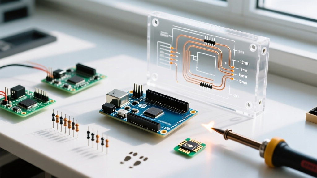
- Header Footprint: Use two 15-pin female headers. Set the row spacing exactly to 0.6 inches (15.24 mm). Do not attempt to route traces between the two inner rows of pins; the physical body of the Nano's USB-B or USB-C overhangs this area on many clones.
- Trace Widths: For standard 20mA GPIO signal lines, 8-mil to 10-mil traces are sufficient. For 5V or 3.3V power distribution, use a minimum of 50-mil traces. For motor or high-current ground returns, use 100-mil traces with 1oz copper weight, or apply solder mask relief to allow for solder flooding.
- Decoupling Capacitors: Always place a 100nF (0.1µF) ceramic capacitor as close to the VCC and GND pins of the Nano header as physically possible. This mitigates high-frequency noise injected by switching power supplies or inductive loads.
Advanced Troubleshooting: Logic Levels and Brownouts
Even with the correct physical shield, electrical mismatches cause 80% of Nano project failures. Here is how to diagnose and resolve the two most common issues.
The 3.3V Logic Level Trap
If you are using a Nano 33 IoT or RP2040 Connect with a shield designed for the 5V Classic Nano, the 3.3V logic HIGH output from the Nano may not cross the $V_{IH}$ (Input Voltage High) threshold of the shield's onboard ICs (like the HC595 shift register or older L298N motor drivers). According to SparkFun's comprehensive guide on logic levels, a 5V TTL device typically requires a minimum of 2.0V to read a HIGH, but CMOS devices may require up to 70% of VCC (3.5V).
The Fix: Integrate a bidirectional logic level converter (like the Texas Instruments TXB0104 or standard MOSFET-based modules) between the Nano's GPIO pins and the shield's inputs. Never rely on internal pull-up resistors to bridge this gap.
USB Power Backfeed and Brownouts
When prototyping with a Nano plugged into an expansion board, developers often leave the USB cable connected to the IDE while also powering the shield via its external DC barrel jack or terminal block. If the external voltage exceeds the USB 5V by more than 0.3V, current will backfeed through the Nano's internal Schottky protection diode into your computer's USB port. This can trip your motherboard's overcurrent protection or permanently damage the Nano's USB controller.
The Fix: When using an external power source on your Nano shield, physically disconnect the USB cable, or use a USB cable with the VCC (red) wire severed. For production firmware, implement a software-based brownout detection (BOD) routine in your Arduino sketch to safely write critical data to EEPROM before the voltage drops below 2.7V.
Final Sourcing and Assembly Recommendations
When assembling your Nano to its shield, avoid using standard low-profile female headers if your expansion board features tall components (like electrolytic capacitors or relay modules) near the center footprint. The Nano's underside features exposed solder joints for the crystal oscillator and reset switch that can short against tall components. Use stacking headers with 11mm or 15mm risers to ensure adequate physical clearance. For a complete overview of the Nano's pinout and hardware limitations, always cross-reference your design with the official Arduino Nano Documentation before finalizing your PCB layout or wiring harness.