
The Evolution of the Nano Footprint
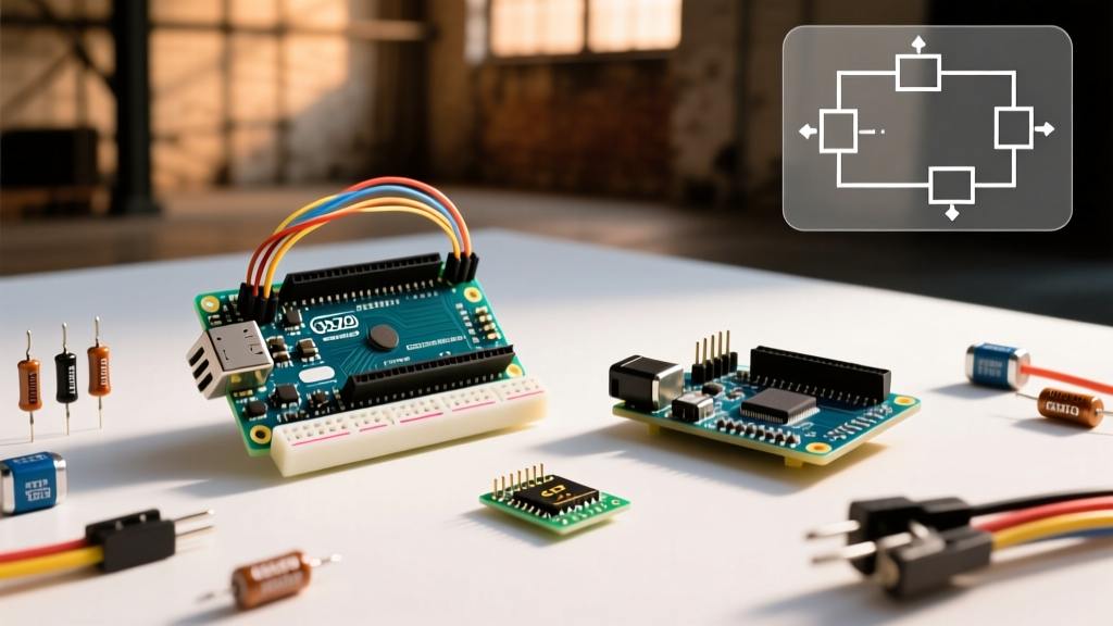
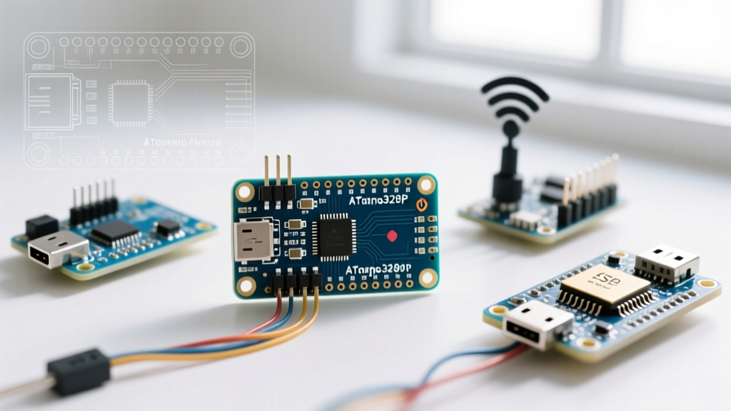
Since its initial release in 2008, the classic Arduino Nano has been the backbone of compact DIY electronics. Measuring just 18x30mm and designed to plug directly into a standard breadboard, its physical footprint has become an industry standard. However, as we navigate the maker landscape in 2026, the 'Nano' is no longer just a single board with an ATmega328P microcontroller. It has evolved into a diverse ecosystem of specialized microcontrollers. Understanding the Arduino Nano pin out requires looking beyond the classic silkscreen and recognizing the critical architectural shifts—particularly the transition from 5V to 3.3V logic—across the modern Nano family.
Classic Arduino Nano Pin Out Breakdown
The original Nano, still widely available via third-party clones for $4 to $6 (and officially from Arduino for around $24), is built around the Microchip ATmega328P or ATmega168. It operates at 5V logic and 16MHz. Below is the definitive mapping for the classic board's 30 through-hole pads.
| Pin Label | Type | Primary Function | Alternate / Peripheral Function | Current / Voltage Limits |
|---|---|---|---|---|
| D0 (RX) | Digital | UART Receive | - | 5V, 20mA max |
| D1 (TX) | Digital | UART Transmit | - | 5V, 20mA max |
| D2 - D9 | Digital | GPIO / PWM | D3, D5, D6, D9 support Hardware PWM | 5V, 20mA max |
| D10 | Digital | Hardware SPI SS | PWM, GPIO | 5V, 20mA max |
| D11 | Digital | Hardware SPI MOSI | PWM, GPIO | 5V, 20mA max |
| D12 | Digital | Hardware SPI MISO | GPIO | 5V, 20mA max |
| D13 | Digital | Hardware SPI SCK / Built-in LED | GPIO | 5V, 20mA max |
| A0 - A3 | Analog | 10-bit ADC Inputs | Can be used as Digital GPIO (D14-D17) | 5V, 20mA max |
| A4 | Analog | ADC Input / Hardware I2C SDA | Digital GPIO (D18) | 5V, 20mA max |
| A5 | Analog | ADC Input / Hardware I2C SCL | Digital GPIO (D19) | 5V, 20mA max |
| A6 / A7 | Analog | ADC Inputs ONLY | No digital pull-ups, no GPIO output | Analog Input Only |
| VIN | Power | Unregulated Input | Recommended 7V - 12V DC | Depends on onboard linear regulator |
| 5V | Power | Regulated 5V Output | Directly tied to USB 5V via diode | ~500mA via USB, ~200mA via VIN |
| 3V3 | Power | 3.3V Regulated Output | Generated by onboard AMS1117-3.3 | 50mA max absolute limit |
The Nano Ecosystem: Variant Pinout Compatibility
When sourcing components for a new project, you will encounter several modern boards that share the exact 18x30mm physical footprint and DIP-30 breadboard spacing. However, their internal architectures and logic levels vary drastically. Failing to account for these differences is the leading cause of fried microcontrollers in advanced prototyping.
1. Arduino Nano Every (ATmega4809)
Priced around $12, the Every retains the 5V logic of the classic but upgrades to the ATmega4809. The physical pinout is identical, but the Every introduces alternate pin multiplexing. For example, you can remap the hardware UART and I2C pins via software registers, freeing up A4 and A5 for analog use. It also features a much more robust onboard 5V regulator capable of sourcing higher currents than the classic clone boards.
2. Arduino Nano 33 IoT & Nano RP2040 Connect
These boards represent the first major ecosystem trap for beginners. While they fit the exact same breadboard footprint, they operate at 3.3V logic.
Critical Warning: Connecting a standard 5V I2C sensor (like the classic MPU6050 or LCD1602 backpack) directly to the A4/A5 pins of a Nano 33 IoT or RP2040 Connect will backfeed 5V into the 3.3V microcontroller, permanently damaging the silicon. You must use a bidirectional logic level shifter (e.g., Texas Instruments TXS0108E) or a BSS138 MOSFET circuit when interfacing 5V legacy shields with 3.3V Nano variants.Furthermore, the RP2040 Connect utilizes the Raspberry Pi RP2040 dual-core Cortex-M0+, meaning peripheral assignments (like SPI1 vs SPI0) are handled via the PIO (Programmable I/O) and software mapping rather than fixed hardware traces.
3. Arduino Nano ESP32 (ESP32-S3)
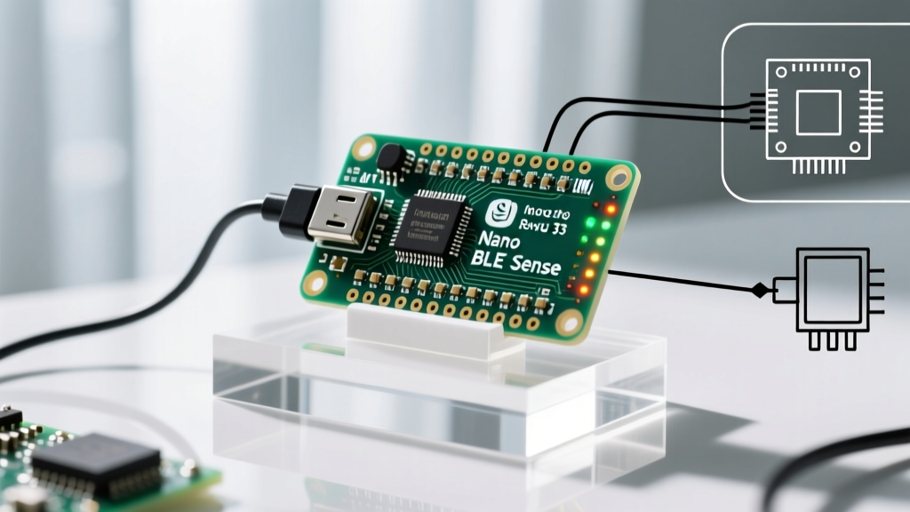
Released to bring Wi-Fi and Bluetooth 5 to the Nano footprint, the Arduino Nano ESP32 operates at 3.3V logic but features a USB-C connector. The pinout silkscreen matches the classic Nano (D2, D3, A0, etc.), but under the hood, these map to specific ESP32-S3 GPIOs.
Edge Case - Strapping Pins: When designing a custom PCB shield for the Nano ESP32, be aware that pins D0 (GPIO0), D3 (GPIO3), and D4 (GPIO46) are strapping pins. If you pull these high or low with external sensors during boot, the ESP32 may enter flash download mode or fail to execute your sketch. Always use 10kΩ pull-up/pull-down resistors with caution on these specific pads.
Power Delivery and the ICSP Header
The power delivery ecosystem across the Nano family requires careful thermal management. On the classic Nano and cheap third-party clones, the VIN pin routes through a linear regulator (often a generic AMS1117-5.0). If you supply 12V to VIN and draw 100mA from the 5V pin, the regulator must dissipate (12V - 5V) * 0.1A = 0.7 Watts of heat. In the confined space of a Nano enclosure, this will trigger thermal shutdown within minutes.
Best Practice: For any Nano project drawing more than 150mA (e.g., driving WS2812B LED strips or multiple servos), bypass the onboard regulator entirely. Supply a regulated 5V directly to the 5V pin, ensuring your external power supply is highly stable. Never exceed 5.5V on the 5V pin, as it directly feeds the microcontroller's VCC rail.
Additionally, the 2x3 ICSP header present on the classic Nano and Nano Every provides direct access to the SPI bus (MISO, MOSI, SCK) and the RESET pin. This is essential for burning custom bootloaders via an ISP programmer or interfacing with legacy AVR shields that route SPI exclusively through the ICSP header rather than the D11-D13 digital pins.
Frequently Asked Questions
Can I use analog pins A6 and A7 as digital outputs?
No. On the classic ATmega328P-based Nano, A6 and A7 are hardwired directly to the internal ADC multiplexer. They lack the digital data direction registers (DDRx) required to function as digital inputs or outputs. If you need extra digital pins, use A0-A5 as D14-D19.
Why does my Nano clone show up as an unknown USB device?
Cheap clones often substitute the official FTDI or CH340 USB-to-Serial chip with a counterfeit CH340G or a poorly soldered micro-USB port. Furthermore, the classic Nano uses a Mini-B connector, which is prone to mechanical failure. If the data lines (D+ / D-) lose contact, the board will draw power but fail to enumerate on your PC. Upgrading to an official Nano or a modern USB-C variant like the Nano ESP32 eliminates this hardware failure point.
How do I wire I2C pull-up resistors on the Nano?
The classic Nano's internal pull-ups are roughly 20kΩ to 50kΩ, which is too weak for reliable I2C communication at 400kHz (Fast Mode). When wiring multiple I2C devices on A4 (SDA) and A5 (SCL), you must add external 4.7kΩ pull-up resistors tied to the 5V rail. If using a 3.3V Nano variant, tie the 4.7kΩ resistors to the 3V3 pin.
For comprehensive hardware schematics and legacy documentation, refer to the official Arduino hardware archives. Understanding the nuances of the Arduino Nano pin out across its varied ecosystem ensures your designs remain robust, scalable, and protected from logic-level mismatches.