
Introduction to the nRF52840 Powerhouse
The Arduino Nano 33 BLE (model ABX00030) represents a massive leap from the classic ATmega328P-based Nano. Built around Nordic Semiconductor's nRF52840 System-on-Chip (SoC), it features a 32-bit ARM Cortex-M4F processor running at 64 MHz, 1MB of Flash memory, and 256KB of SRAM. As of 2026, this board retails for approximately $24.50, making it a premium but highly accessible choice for low-power IoT and wearable applications. However, transitioning to this board requires a fundamental understanding of its architecture, specifically the Arduino Nano 33 BLE pinout, which differs drastically from its 5V predecessors.
In this guide, we will decode the physical header layout, navigate the critical voltage constraints, and build a first-project Bluetooth Low Energy (BLE) environmental beacon. For comprehensive hardware schematics, always refer to the Arduino Nano 33 BLE Official Hardware Docs.
Decoding the Arduino Nano 33 BLE Pinout
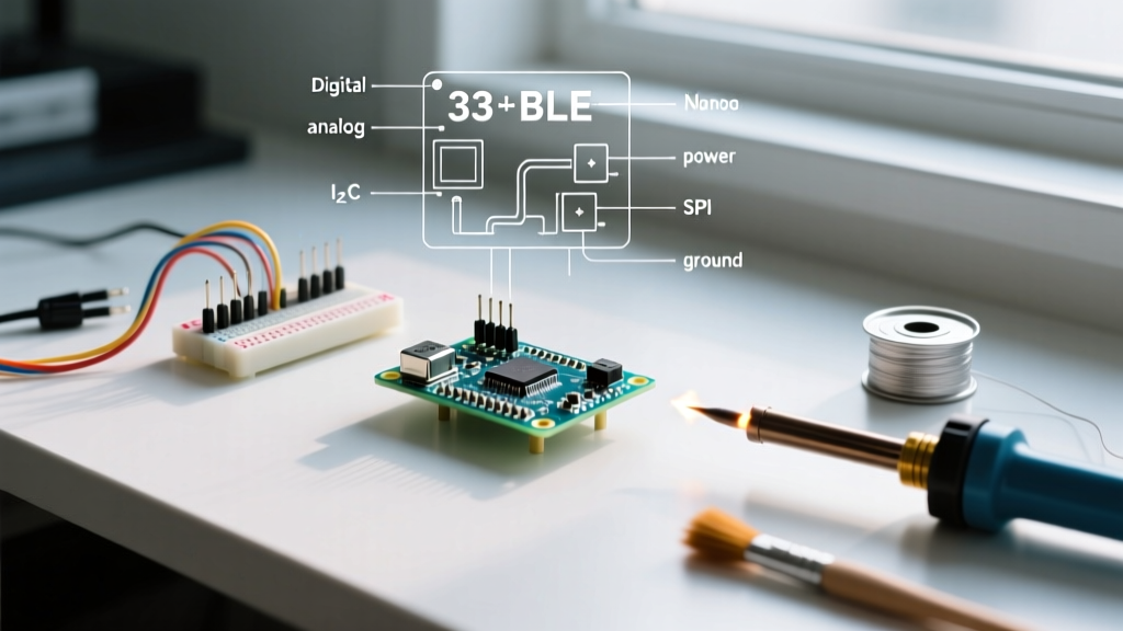
The board features 30 pins (15 per side) spaced at standard 0.6-inch (15.24mm) width, making it breadboard-friendly. Unlike the classic Nano, every single I/O pin on this board operates at 3.3V logic. Applying 5V to any digital or analog pin will instantly and permanently destroy the nRF52840 silicon.
CRITICAL WARNING: The nRF52840 absolute maximum voltage rating on I/O pins is 3.6V. Do not use standard 5V sensors (like the HC-SR04 ultrasonic sensor or 5V OLEDs) without a bidirectional logic level shifter.
Pinout Matrix & Functional Mapping
Below is the functional breakdown of the headers. Note that many pins share secondary functions for hardware communication protocols.
| Pin Label | Primary Function | Alternate / Protocol Function | Voltage / Notes |
|---|---|---|---|
| TX / RX | Digital I/O (D1 / D0) | UART1 (Serial1) | 3.3V Logic |
| D2 - D9 | Digital I/O, PWM | D2-D9 support PWM via Mbed OS | 3.3V Logic, 11mA max per pin |
| D10 | Digital I/O, PWM | SPI Chip Select (CS) | 3.3V Logic |
| D11 / D12 / D13 | Digital I/O, PWM | SPI (COPI / CIPO / SCK) | 3.3V Logic |
| A0 - A3 | Analog Input (12-bit ADC) | Digital I/O (D14-D17) | 3.3V Max Input |
| A4 / A5 | Analog Input | I2C (SDA / SCL) | 3.3V, Internal pull-ups disabled |
| A6 / A7 | Analog Input ONLY | No digital I/O capability | 3.3V Max Input |
| 3V3 | Power Output | Onboard Regulator Output | 3.3V, 800mA max capacity |
| VIN | Power Input | Unregulated Input | Accepts 5V - 21V DC |
| VUSB | USB Power (5V) | Requires bottom solder jumper | 5V from USB, not default enabled |
The VUSB Solder Jumper "Gotcha"
A common point of confusion for beginners mapping the Arduino Nano 33 BLE pinout is the absence of 5V on the headers by default. The board includes a VUSB pad on the bottom of the PCB. To route the 5V from the USB connector to the VUSB header pin (useful for powering 5V peripherals via a level shifter), you must bridge this tiny solder jumper on the underside of the board. Without this bridge, the VUSB pin outputs nothing.
Hardware Setup: Wiring an External I2C Sensor
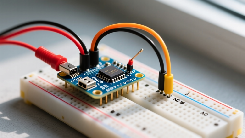
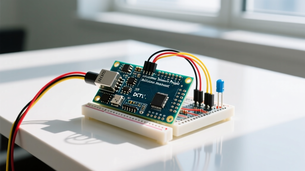
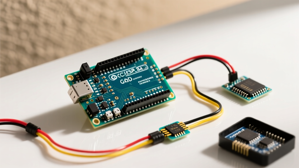
For our first project, we will bypass the onboard LSM9DS1 IMU and wire an external BME280 environmental sensor (Temperature, Humidity, Pressure) via I2C to broadcast data over BLE. The BME280 is a 3.3V native sensor, making it perfectly compatible with our board.
Wiring Diagram (BME280 to Nano 33 BLE)
- VIN (BME280) → 3V3 (Nano 33 BLE)
- GND (BME280) → GND (Nano 33 BLE)
- SCL (BME280) → A5 (Nano 33 BLE I2C Clock)
- SDA (BME280) → A4 (Nano 33 BLE I2C Data)
Expert Note on I2C Pull-ups: The nRF52840 does not enable internal I2C pull-up resistors by default to save power. While most Adafruit/SparkFun BME280 breakout boards include onboard 4.7kΩ pull-up resistors, if you are using a bare BME280 module from a generic marketplace, you must add external 4.7kΩ resistors between SDA/3V3 and SCL/3V3, or the I2C bus will hang indefinitely.
Software Configuration & First BLE Sketch
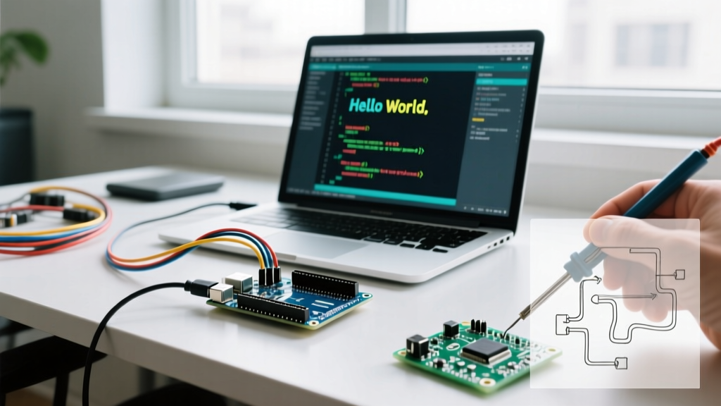
To program the board, ensure you are using Arduino IDE 2.x. Navigate to Boards Manager, search for "Arduino Mbed OS Nano Boards", and install the latest package. Select Arduino Nano 33 BLE from the board dropdown.
We will use the official ArduinoBLE library to create a custom BLE Service and Characteristic. For deeper protocol specifications, refer to the Bluetooth SIG BLE Technology Overview.
The BLE Beacon Code
Install the ArduinoBLE and Adafruit BME280 Library via the Library Manager, then upload the following sketch:
#include <ArduinoBLE.h>
#include <Wire.h>
#include <Adafruit_Sensor.h>
#include <Adafruit_BME280.h>

Adafruit_BME280 bme;

// Define custom BLE Service and Characteristics
BLEService envService("180F"); // Battery/Env generic service
BLEFloatCharacteristic tempChar("2A1C", BLERead | BLENotify);
BLEFloatCharacteristic humChar("2A6F", BLERead | BLENotify);

void setup() {
  Serial.begin(115200);
  while (!Serial); // Wait for serial monitor

  // Initialize I2C and BME280
  if (!bme.begin(0x76)) {
    Serial.println("BME280 not found on I2C. Check A4/A5 wiring.");
    while (1);
  }

  // Initialize BLE
  if (!BLE.begin()) {
    Serial.println("Starting BLE failed!");
    while (1);
  }

  BLE.setLocalName("Nano33BLE-Env");
  BLE.setAdvertisedService(envService);

  envService.addCharacteristic(tempChar);
  envService.addCharacteristic(humChar);
  BLE.addService(envService);

  BLE.advertise();
  Serial.println("BLE Peripheral is now advertising...");
}

void loop() {
  BLEDevice central = BLE.central();

  if (central) {
    Serial.print("Connected to central: ");
    Serial.println(central.address());

    while (central.connected()) {
      float t = bme.readTemperature();
      float h = bme.readHumidity();

      tempChar.writeValue(t);
      humChar.writeValue(h);

      delay(2000); // Broadcast every 2 seconds
    }
    Serial.print("Disconnected from central: ");
    Serial.println(central.address());
  }
}
Real-World Troubleshooting & Edge Cases
Working with ARM Cortex-M4F boards running Mbed OS introduces different failure modes compared to AVR boards. If your project fails, check these specific edge cases:
1. The "Blinking Red LED" Hard Fault
If the onboard RGB LED rapidly blinks red in a repeating pattern, the nRF52840 has encountered a HardFault. This is almost always caused by:
- Memory Overflow: Exceeding the 256KB SRAM limit (common if allocating massive arrays for local data logging).
- I2C Bus Lockup: A missing pull-up resistor causing the Wire library to hang the OS thread indefinitely.
- Power Brownout: Attempting to draw more than 800mA from the 3V3 regulator, triggering the hardware watchdog.
2. BLE Connection Drops on Mobile
If your iOS or Android device connects but immediately drops the connection, ensure you are not overwhelming the BLE stack. The nRF52840 has a specific connection interval. Sending data via writeValue() faster than every 20-50 milliseconds without a proper handshake will cause the mobile OS to terminate the link to preserve battery. Always implement a delay() or use a non-blocking millis() timer of at least 100ms between characteristic updates.
3. Serial Port Not Appearing in IDE
The Nano 33 BLE uses a native USB implementation (not a secondary USB-to-Serial chip like the CH340). If the board crashes before USB initialization, the COM port will vanish. Fix: Double-tap the reset button quickly. This forces the board into the Mbed OS bootloader mode (the LED will pulse), allowing you to select the port and upload a blank sketch to recover the board.
Conclusion
Mastering the Arduino Nano 33 BLE pinout is the first step toward building ultra-low-power, professional-grade IoT devices. By respecting the strict 3.3V logic limits, understanding the I2C pull-up requirements, and leveraging the native BLE stack, you can bypass the limitations of older 8-bit microcontrollers. Whether you are building a wearable health monitor or a remote agricultural sensor, the nRF52840 provides the processing headroom and wireless efficiency required for modern 2026 edge-computing projects.