
The Intersection of Hardware and Community Code
The Arduino Nano remains one of the most ubiquitous microcontroller boards in the DIY electronics space. Measuring just 18x45mm with a standard 0.6-inch (15.24mm) breadboard-friendly row spacing, its physical footprint is only half the story. In 2026, the true power of the Nano ecosystem lies in its massive community and library support. However, successfully leveraging thousands of third-party GitHub repositories and Arduino Library Manager packages requires a deep, precise understanding of the arduino nano pin layout and how it maps to underlying hardware protocols.
Whether you are using a $24.50 genuine ATmega328P Classic, a $21.00 Nano ESP32, or a $4.00 third-party clone, community libraries abstract away much of the low-level register manipulation. But when those abstractions leak—or when you attempt to port legacy code to newer Nano variants—knowing exactly how physical silkscreen labels translate to software-defined GPIOs, hardware interrupts, and timer-bound pins is the difference between a working prototype and hours of frustrating debugging.
The Classic ATmega328P: Legacy Support and Pin Traps
The original Arduino Nano (and its most common clone variants) relies on the Microchip ATmega328P. Because this chip has been the backbone of the Arduino ecosystem for over a decade, the vast majority of community libraries—such as Adafruit GFX, FastLED, and SparkFun BME280—were written with its specific pinout in mind.
According to the official Arduino Nano Documentation, the board exposes 14 digital pins (D0-D13) and 8 analog pins (A0-A7). However, community library integration often fails when developers misunderstand the hardware limitations of specific pins.
Communication Protocol Matrix
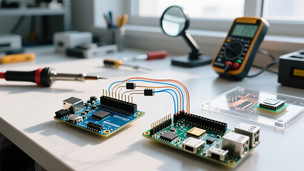
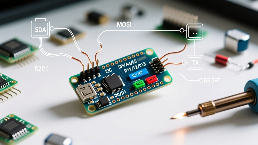
When integrating sensor libraries, you must map the physical pins to the correct hardware buses. Here is how the community-standard libraries expect the Classic Nano to be wired:
| Physical Pin | Protocol / Function | Standard Community Library | Common Failure Mode |
|---|---|---|---|
| A4 (SDA), A5 (SCL) | I2C Bus | Wire.h, Adafruit Sensor Bus |
Missing 4.7kΩ pull-up resistors on clone boards lacking them. |
| D10 (SS), D11 (MOSI), D12 (MISO), D13 (SCK) | Hardware SPI | SPI.h, SD Card FAT32 Libs |
Using D10 for unrelated digital I/O, which disables the SPI controller. |
| D0 (RX), D1 (TX) | Hardware UART | Serial, Bluetooth HC-05 libs |
Leaving USB connected while uploading via external FTDI, causing bus contention. |
| D2, D3 | External Interrupts (INT0, INT1) | Rotary Encoder libs, PinChangeInterrupt | Using D4+ for hardware interrupts (must use PCINT libraries instead). |
The A6 and A7 Analog Trap
One of the most frequent issues reported in community forums involves pins A6 and A7. Unlike A0 through A5, which are multiplexed and can function as both analog inputs and digital I/O, A6 and A7 are strictly analog inputs on the ATmega328P. They lack internal digital pull-up/pull-down resistors and cannot be read via digitalRead(). If a community library for a button matrix or digital sensor attempts to initialize A6 as a digital input, it will silently fail, returning floating or static values.
Navigating the Modern Ecosystem: Nano Every and Nano ESP32
As of 2026, the Arduino Nano family has expanded significantly. While the physical footprint and general arduino nano pin layout silkscreen remain similar, the underlying silicon has changed, creating massive implications for community library support.
The ATmega4809 Pinmux Challenge (Nano Every)
The Nano Every utilizes the ATmega4809, which features a vastly different PORTMUX (Port Multiplexer) architecture compared to the 328P. While the Arduino core team did an excellent job mapping the standard Wire and SPI libraries to the correct physical pins, third-party libraries that rely on direct port manipulation (e.g., writing directly to PORTB or PORTD registers to achieve high-speed bit-banging) will completely fail on the Every. Furthermore, the Nano Every supports alternative I2C and UART pin mappings via the PORTMUX register, a feature that advanced community forks like MegaCoreX expose, but standard libraries do not natively support without manual configuration.
ESP32-C3 Strapping Pins and GPIO Mapping (Nano ESP32)
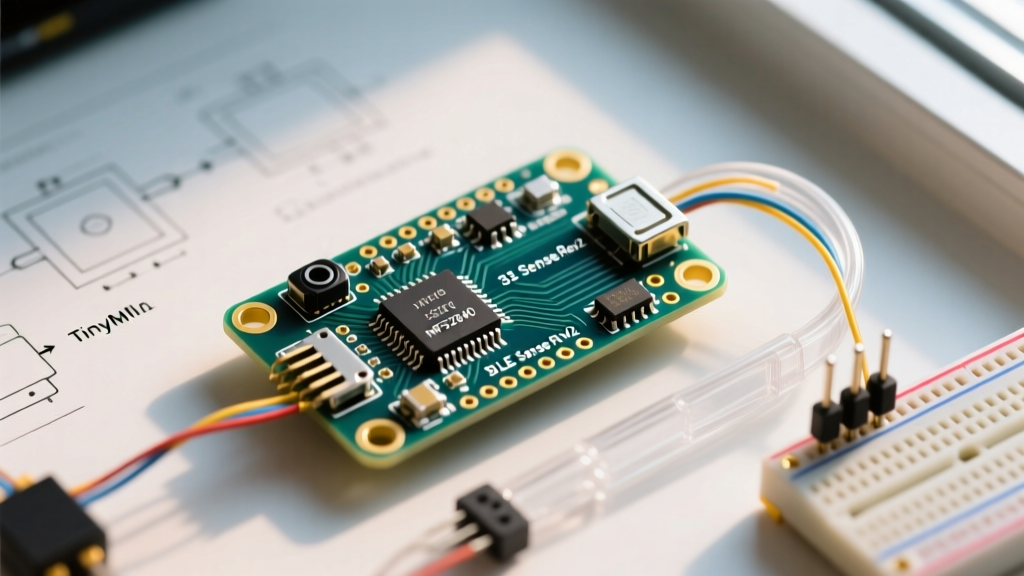
The Nano ESP32 has become a favorite for IoT projects due to its built-in Wi-Fi and Bluetooth. However, its physical pin labels (D2, D3, etc.) do not directly correspond to the internal ESP32-C3 GPIO numbers. For instance, the silkscreen pin D2 maps to GPIO5, and D3 maps to GPIO4.
Expert Warning: The ESP32-C3 features specific "strapping pins" that dictate boot behavior. On the Nano ESP32, GPIO8 (mapped to physical pin D4) and GPIO9 (mapped to D5) are sampled during reset. If a community library configures these pins as outputs and drives them LOW during the boot sequence, the Nano ESP32 will enter a continuous boot loop, failing to execute your
setup()function entirely. Always consult the Nano ESP32 Hardware Docs before assigning boot-critical peripherals to these pins.
Hacking Community Libraries for Custom Pinouts
When a community library hardcodes pin definitions that clash with your specific Nano wiring or shield, you must intervene at the software level. Here are actionable strategies for resolving pin layout conflicts in 2026:
- Override
#defineMacros: Many display libraries (like U8g2 or TFT_eSPI) use user-setup header files. Never modify the core library files directly, as they will be overwritten during a Library Manager update. Instead, use the library's designatedUser_Setup.hfile to remap the SPI or I2C pins to match your physical Nano wiring. - Resolving SoftwareSerial Conflicts: The standard
SoftwareSeriallibrary disables interrupts while transmitting, which can cause data loss in concurrent sensor reads. The community-developedAltSoftSeriallibrary solves this by using hardware timers. However, on the Classic Nano,AltSoftSerialis hardcoded to use D8 (RX) and D9 (TX). If your physical layout requires different pins, you must switch toNeoSWSerial, which supports any pins but maxes out at 19,200 baud. - FastLED and Hardware SPI: When driving WS2812B NeoPixels, the FastLED library can use hardware SPI for ultra-reliable, interrupt-free data transmission. On the Classic Nano, this mandates using pin D11 (MOSI). If your physical layout has D11 routed to an SPI SD card module, you cannot use hardware SPI for LEDs simultaneously; you must fall back to bit-banging on a free digital pin, accepting the risk of flickering if interrupts fire during the LED update cycle.
Leveraging Community Board Managers for Deep Pin Control
To truly master the Nano ecosystem, rely on community-maintained board packages rather than just the default Arduino cores. By adding third-party Board Manager URLs in the Arduino IDE preferences, you unlock advanced pin-mapping features.
For example, installing the MiniCore package by MCUdude allows you to utilize the "Breadboard" or "ATmega328" variants with custom clock speeds (e.g., running a clone Nano at 8MHz internal for low-power battery applications). MiniCore provides a highly optimized pins_arduino.h file that correctly maps analog pins and enables the use of the often-forgotten PB6 and PB7 pins (XTAL1/XTAL2) as standard digital I/O when the internal oscillator is selected—a hardware trick that the default Arduino core completely hides from the user.
Summary: Hardware Dictates Software
The physical arduino nano pin layout is more than just a silkscreen guide; it is the foundational contract between your hardware and the community's software. By understanding the strict boundaries of hardware protocols, the architectural differences between the Classic, Every, and ESP32 variants, and the specific failure modes of popular libraries, you can seamlessly integrate third-party code into your projects. Always verify the underlying microcontroller architecture before flashing legacy code to modern Nano boards, and leverage community board managers to unlock the full potential of your hardware.