
Decoding the Arduino Uno Scheme: From Internal Schematic to First Project
When beginners search for an Arduino Uno scheme, they are usually looking for one of two things: the internal electronic schematic of the board itself, or a wiring scheme (circuit diagram) for their first project. Understanding both is the cornerstone of moving from a novice who simply copies code to an engineer who designs reliable embedded systems. In this comprehensive setup and first-project tutorial, we will dissect the internal architecture of the classic Arduino Uno, map its pinout limitations, and walk through a precise wiring scheme for an interactive pushbutton LED circuit.
The Internal Arduino Uno Scheme: What is Actually on the Board?
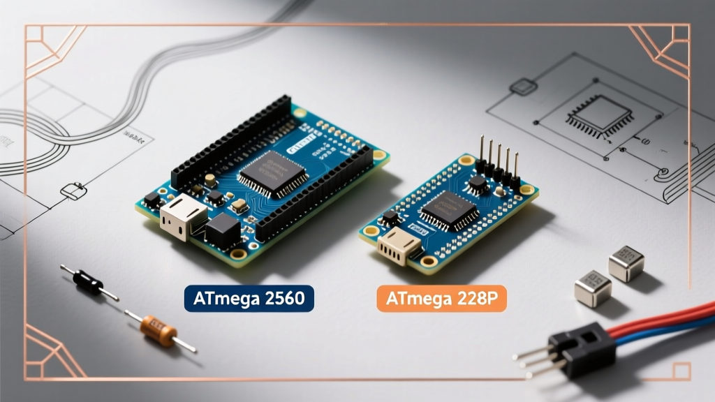
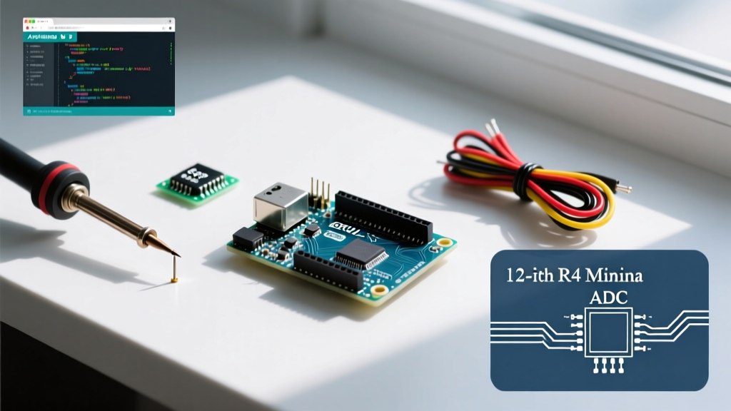
Before wiring external components, you must understand the brain and the supporting cast on the PCB. Whether you are using the legacy ATmega-based Uno R3 (retailing around $27.50) or the newer ARM-based Uno R4 Minima (approximately $19.50 in 2026), the core scheme revolves around power regulation, USB-to-Serial communication, and the primary microcontroller.
Core Components of the Classic R3 Schematic
- Main MCU (ATmega328P-PU): The 28-pin DIP microcontroller operating at 16 MHz via an external quartz crystal oscillator. It features 32KB of ISP flash memory and 2KB of SRAM.
- USB-to-Serial Converter (ATmega16U2): Unlike older boards that used FTDI chips, the R3 scheme utilizes a dedicated ATmega16U2 programmed as a USB-to-serial bridge, allowing for custom firmware flashing via the ICSP headers.
- Voltage Regulation (NCP1117ST50T3G): A linear regulator that steps down unregulated voltage from the barrel jack or VIN pin to a stable 5V logic level.
For a deeper dive into the official traces and component placement, you can review the official Arduino Uno R3 hardware documentation, which provides the full PDF schematic and EagleCAD files.
The Pinout Scheme: Mapping Limits and Logic Levels
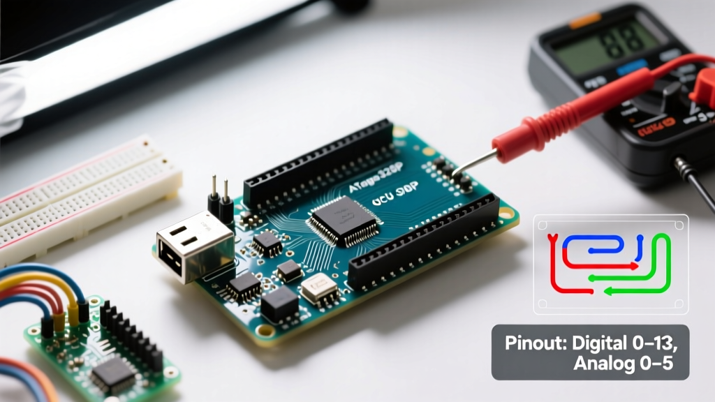
A critical mistake beginners make when designing a project scheme is ignoring the electrical limits of the microcontroller pins. The ATmega328P is robust, but it is not invincible. Below is the definitive pinout scheme and limitation matrix you must reference before wiring any load.
| Pin Group | Designations | Logic Voltage | Max Current Limit | Primary Use Case |
|---|---|---|---|---|
| Digital I/O | D0 - D13 | 5V (HIGH) | 20mA absolute max (15mA recommended) | LEDs, relays (via transistor), pushbuttons |
| Analog Inputs | A0 - A5 | 0-5V Input | N/A (High impedance) | Potentiometers, analog sensors (LDR, TMP36) |
| Power Output | 5V Pin | 5V Regulated | Limited by regulator thermal mass (~800mA max) | Powering external logic ICs or sensors |
| Power Output | 3.3V Pin | 3.3V Regulated | 50mA max (via onboard LP2985) | ESP8266 modules, 3.3V logic sensors |
| Communication | D0 (RX), D1 (TX) | 5V TTL | 20mA | Serial debugging, GPS modules |
Note: While a single pin can source 20mA, the combined total current drawn from all I/O pins simultaneously must not exceed 200mA to prevent permanent silicon damage.
Your First Project Scheme: Interactive Pushbutton LED
Let us transition from theory to practice. Your first project scheme will involve reading a digital input (a tactile pushbutton) to control a digital output (a 5mm LED). While many tutorials use a simple 'pull-down' resistor scheme, we will implement a more robust wiring scheme utilizing the microcontroller's internal pull-up resistors. This reduces component count and wiring complexity.
Bill of Materials (BOM)
- 1x Arduino Uno (R3 or R4)
- 1x Standard 5mm Red LED (Forward Voltage: ~2.0V)
- 1x 220Ω 1/4W Carbon Film Resistor
- 1x 6x6mm Tactile Pushbutton Switch
- 1x Solderless Breadboard (830 tie-points)
- 3x 22 AWG Solid Core Jumper Wires
Calculating the Current-Limiting Resistor
Never wire an LED directly to a digital pin without a current-limiting resistor; you will destroy both the LED and the ATmega328P pin. We use Ohm's Law to find the exact resistor value for our scheme:
R = (V_source - V_forward) / I_desired
R = (5.0V - 2.0V) / 0.015A (15mA target)
R = 3.0 / 0.015 = 200Ω
Since 200Ω is not a standard E12 resistor value, we step up to the next standard value: 220Ω. This safely limits the current to ~13.6mA, well within the 20mA pin limit.
Step-by-Step Wiring Scheme
- Power Rails: Connect a red wire from the Arduino '5V' pin to the breadboard's positive (+) rail. Connect a black wire from 'GND' to the negative (-) rail.
- LED Output Circuit: Insert the LED's anode (long leg) into row 10. Connect one lead of the 220Ω resistor to row 10 (sharing the anode tie-point) and the other lead to row 15. Run a jumper wire from row 15 to Arduino Digital Pin 8.
- Button Input Circuit: Straddle the pushbutton across the breadboard's center trench. Connect one side of the button to the GND rail. Connect the opposite side to Arduino Digital Pin 2.
By wiring the button directly to ground and utilizing the internal pull-up resistor in our code scheme, the pin reads HIGH (5V) when unpressed, and LOW (0V) when pressed. For a deeper understanding of why floating pins cause erratic behavior, review this excellent guide on pull-up resistors by SparkFun.
The Code Scheme: Logic and IDE Setup
Open the Arduino IDE (version 2.3.x or newer). Under Tools > Board, select 'Arduino Uno'. Ensure your COM port is correctly assigned. The code scheme relies on three core functions: pinMode(), digitalRead(), and digitalWrite().
In the setup() block, configure Pin 8 as an OUTPUT and Pin 2 as an INPUT_PULLUP. The INPUT_PULLUP argument is the magic of this scheme—it activates the internal 20kΩ-50kΩ resistor tied to 5V inside the ATmega328P, eliminating the need for an external resistor on the breadboard.
In the loop() block, read the state of Pin 2. Because of our inverted logic scheme (pressing the button connects the pin to ground), a LOW reading means the button is pressed. Write an if/else statement to set Pin 8 HIGH when the button reads LOW, and LOW otherwise. Upload the sketch. Your LED will now illuminate precisely when the button is actuated.
Advanced Troubleshooting: Scheme Failure Modes
Even with a perfect wiring scheme, physical realities can cause failures. Here are the most common edge cases and how to resolve them:
1. Voltage Regulator Thermal Shutdown
If you power your Arduino Uno via the barrel jack with a 12V adapter and attempt to draw 300mA from the 5V pin to power external sensors, the onboard NCP1117 linear regulator will overheat. The scheme of a linear regulator dictates that it burns excess voltage as heat. Power dissipation is calculated as P = (V_in - V_out) * I. In this case, (12V - 5V) * 0.3A = 2.1 Watts. The SOT-223 package cannot dissipate this without a heatsink, triggering internal thermal shutdown. Solution: Keep barrel jack input voltage between 7V and 9V, or power high-current 5V peripherals via a separate buck converter.
2. Floating Pin Noise
If you forgot to use INPUT_PULLUP and left the pin disconnected when the button is open, the pin acts as an antenna. Electromagnetic interference (EMI) from nearby AC wiring or Wi-Fi routers will induce random voltage spikes, causing the LED to flicker erratically. Always ensure inputs are tied to a known logic state.
3. USB-C vs. Barrel Jack Polarity
While newer clones and the official R4 use USB-C for both power and data, legacy R3 boards use a USB-B connector. If you are using a third-party barrel jack adapter, ensure it is center-positive. Reversing the polarity will instantly destroy the onboard protection diode (usually a 1N4007 or similar M7 diode located near the jack).
Conclusion
Mastering the Arduino Uno scheme requires looking past the colorful block diagrams and understanding the actual electrical pathways, current limits, and logic states at play. By internalizing the board's internal schematic, respecting the pinout limitations, and applying rigorous wiring schemes like the internal pull-up configuration, you lay a foundation that will support you through vastly more complex projects involving I2C sensors, SPI displays, and motor drivers. For further reading on microcontroller pin architectures, consult the Arduino Microcontroller Pin Guide.